Supercharge Your Innovation With Domain-Expert AI Agents!

Leaf spring compression system design

a compression system and spring spring technology, applied in the direction of cell components, final product manufacturing, sustainable manufacturing/processing, etc., can solve the problems of premature structural degradation, affecting battery performance and overall cost, compromising balance, etc., to reduce non-uniform loading of battery cell stack, uniform loading, and uniform loading

Active Publication Date: 2018-08-16
ESS TECHNOLOGY
View PDF2 Cites 8 Cited by
  • Summary
  • Abstract
  • Description
  • Claims
  • Application Information

AI Technical Summary

Benefits of technology

This patent describes a compression system for battery cell stacks that addresses issues related to non-uniform loading and cell stack deflection. The system uses reinforcement bars, springs, and fulcrums to apply a compression load on the cell stack while maintaining uniform loading. The system can adjust the compression load to allow for cell stack expansion and contraction during operation while minimizing costs. Overall, this system provides a solution for maintaining the performance of battery cell stacks under various operating conditions.

Problems solved by technology

These electrodes take part in electrochemical reactions responsible for storing and releasing chemical energy in the battery, and thus affect battery performance and overall costs.
The compression system also tries to accommodate changes in stack height caused by thermal expansion and contraction of the cell stack during operation, although these objectives may compromise the balance of sufficient but not excessive compressive force.
However, the inventors have recognized potential issues with such compression system for cell stacks.
For example, compression loads imposed only at one end of the cell stack may generate asymmetric loading of the cell stack and may generate structural degradation prematurely.
Further, issues related to the compressive loads and expansion, as well as the interactions therebetween, can be particular to flow battery systems.
As another example, coil springs designed to provide loading at the base of the springs and around the periphery of the cell stack may generate non-uniform loading of the cell stack, inducing deflections larger than permitted.
Overly large deflections may cause unstable conditions within the battery cell stack affecting performance of the flow battery.

Method used


Image

  • Leaf spring compression system design
  • Leaf spring compression system design
  • Leaf spring compression system design

Examples


second embodiment

[0024]FIG. 6 shows an exploded view of the battery cell stack. The battery cell stack may be assembled together using tie rods extending through leaf springs (held in reinforcement bars), and pressure plates placed on either side of the cell stack. In addition, a locking assembly comprising a bushing, a collar and a shaft, may be provided to close off or block openings in the cell stack. FIG. 7 shows an example leaf spring (depicted as a beam) with operating loads and fulcrums positioned to direct compressive loads (imposed on a battery cell stack) along active areas of the cell stack. FIG. 8 shows deflection of example leaf springs of the battery cell stacks shown in FIGS. 2-4A. The example leaf springs may be placed at the top, center and bottom of each battery cell stack, with fulcrums positioned at chosen locations along each leaf spring, as shown in FIGS. 3 and 5.

[0025]FIGS. 1-6 show example configurations with relative positioning of the various components of the battery cell ...

first embodiment

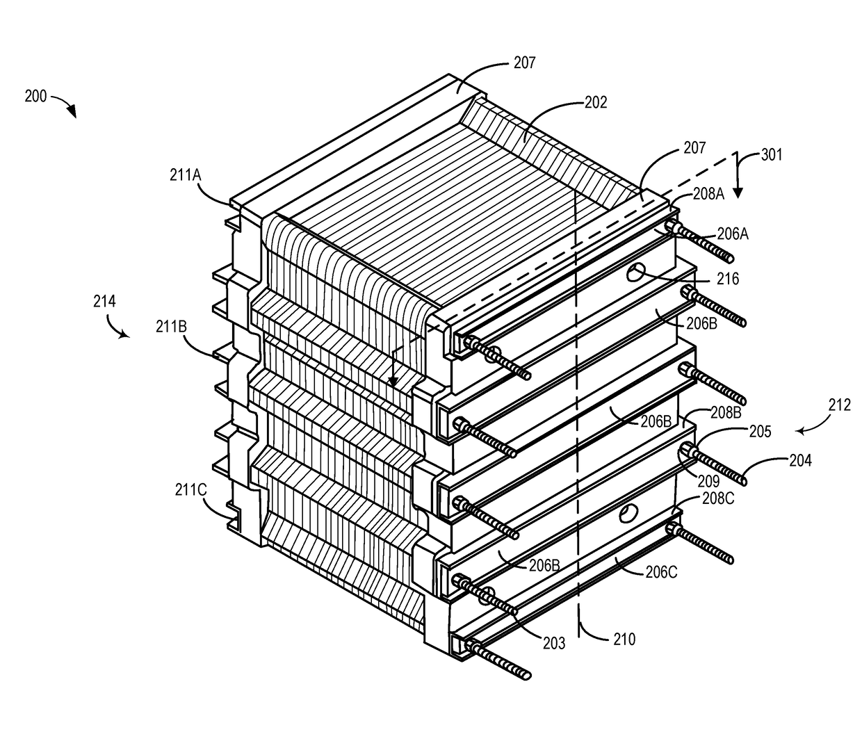
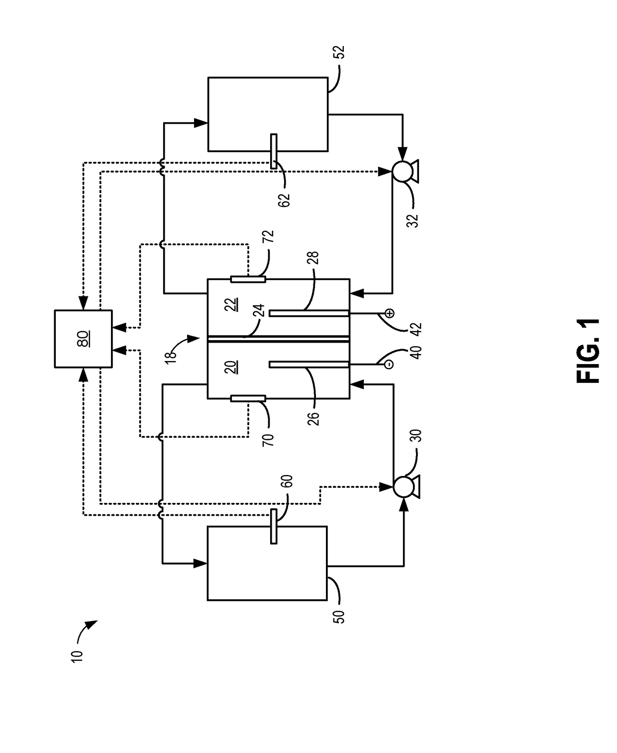
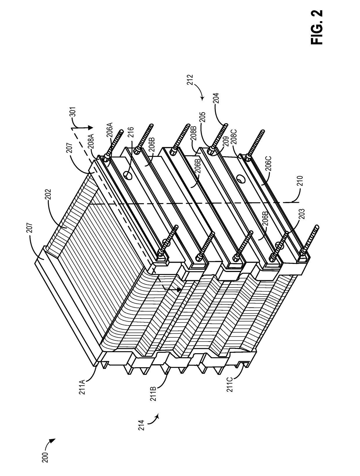
[0040]Referring to FIG. 2, a three-dimensional view of a battery cell stack 200, which may be used as stack 18 of flow battery 10 is shown. The battery cell stack 200 includes a plurality of reactor cells 202 consistent with the embodiments disclosed herein. The reactor cells 202 may be held together by mounting pressure plates 207 and reinforcement bars 208A-C holding leaf springs 206A-C, on either side of the reactor cells, and securing the cell stack using tie rod assemblies 203 and 204. The battery cell stack 200 may include a plurality of openings 216. The openings 216 may be closed off or blocked by a locking assembly or other suitable closing mechanisms such as caps, plugs etc.

[0041]As shown in FIG. 2, the reactor cells 202 in the battery cell stack may be secured together using a plurality of tie rod assemblies 203 and 204, which may be adjustable to apply a uniform compression load across the cell stack. Alternatively, the reactor cells 202 in the battery cell stack may be ...


PUM

PropertyMeasurementUnit
lengthaaaaaaaaaa
widthaaaaaaaaaa
thicknessaaaaaaaaaa

Abstract

A leaf spring compression system comprising a mechanical assembly for securing a plurality of leaf springs on a battery cell stack of a flow battery system is disclosed. The cell stack may, comprise: a plurality of cells stacked together to form a flow battery; and a compression system comprising at least two tie rods extending through the plurality of cells clamping a spring acting at opposite ends to compress the cells together, the spring contacting at least two fulcrum elements positioned between the tie rods. In this way, the compression system may exert uniform loading on the battery cell stack, while minimizing deflection of pressure plates attached to the cell stack.

Description

CROSS REFERENCE TO RELATED APPLICATION[0001]This application claims priority to U.S. Provisional Patent Application No. 62 / 458,446, entitled “Leaf Spring Compression System Design,” filed Feb. 13, 2017, the entire contents of which is hereby incorporated by reference in its entirety for all purposes.FIELD[0002]The present description relates generally to methods and systems for a leaf spring compression system for securing a battery cell stack of a flow battery system.BACKGROUND AND SUMMARY[0003]A reduction-oxidation (redox) flow battery is an electrochemical device which converts chemical energy stored in a battery to electrical energy via reverse redox reactions. When depleted, the chemical energy in the battery is restored by applying an electrical current to induce reverse redox reactions.[0004]In general, the redox flow battery includes negative and positive electrodes contained within a battery cell stack. These electrodes take part in electrochemical reactions responsible for...

Claims


Application Information

Patent Timeline
Patent Type & Authority Applications(United States)
IPC IPC(8): H01R4/48H01M8/2485H01M8/248H01M8/0258H01M10/04H01M2/20
CPCH01R4/4809H01M8/2485H01M8/248H01M8/0258H01M10/0468H01M2/208H01M8/18H01R4/489H01M8/188Y02E60/50Y02E60/10Y02P70/50
Inventor EVANS, CRAIG E.CASEY, SEAN
Owner ESS TECHNOLOGY
Features
  • R&D
  • Intellectual Property
  • Life Sciences
  • Materials
  • Tech Scout
  • Unparalleled Data Quality
  • Higher Quality Content
  • 60% Fewer Hallucinations
Learn More