Supercharge Your Innovation With Domain-Expert AI Agents!

Vertical-column pressurized hydraulic vulcanizing machine

A vulcanizer and column technology, applied in the field of column pressurized hydraulic vulcanizers, can solve the problems such as heavy weight of lower pallets, molds and tires, unfavorable design of afterburner cylinders, and increase of thrust of cylinders, and achieve fast afterburner speed. , Short working stroke, the effect of reducing inertia

Inactive Publication Date: 2009-09-23
桂林中昊力创机电设备有限公司
View PDF0 Cites 1 Cited by
  • Summary
  • Abstract
  • Description
  • Claims
  • Application Information

AI Technical Summary

Problems solved by technology

[0005] 1. When the booster cylinder is boosted, it not only needs to provide the clamping force required for the mold to vulcanize the tire, but also needs to overcome the gravity of the lower pallet, mold and tire, which increases the demand for the thrust of the cylinder and virtually increases the cylinder diameter.
[0006] 2. Especially for the vulcanization of giant tires, the weight of the lower pallet, mold and tire is even greater, which is not only a waste of pallet material but also not conducive to the design of the afterburner cylinder, and there are serious structural problems
[0007] 3. It is very inconvenient to operate when changing the mold specifications, the labor intensity is high, and it is easy to affect the accuracy of the equipment

Method used


Image

  • Vertical-column pressurized hydraulic vulcanizing machine
  • Vertical-column pressurized hydraulic vulcanizing machine

Examples


Embodiment Construction

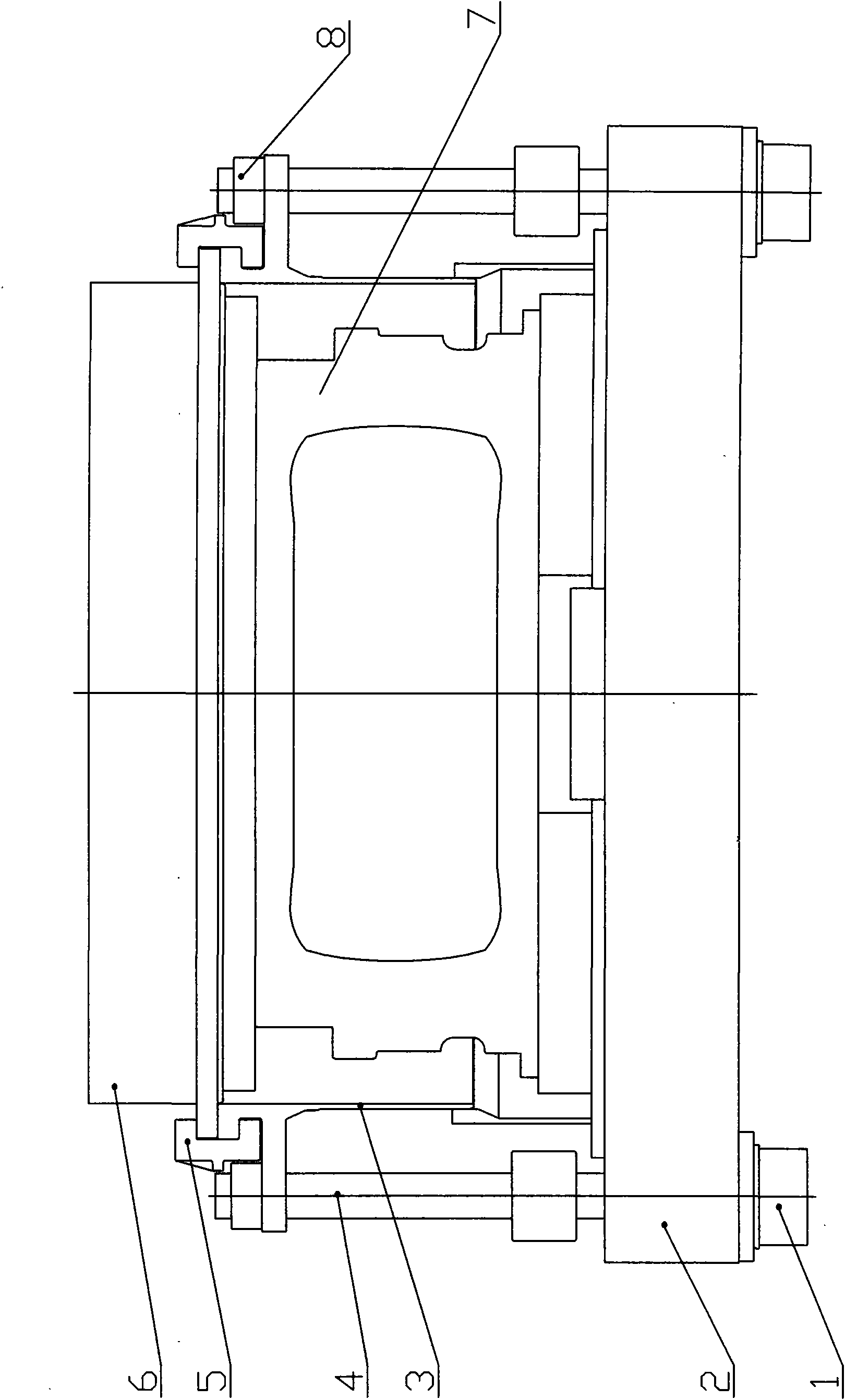
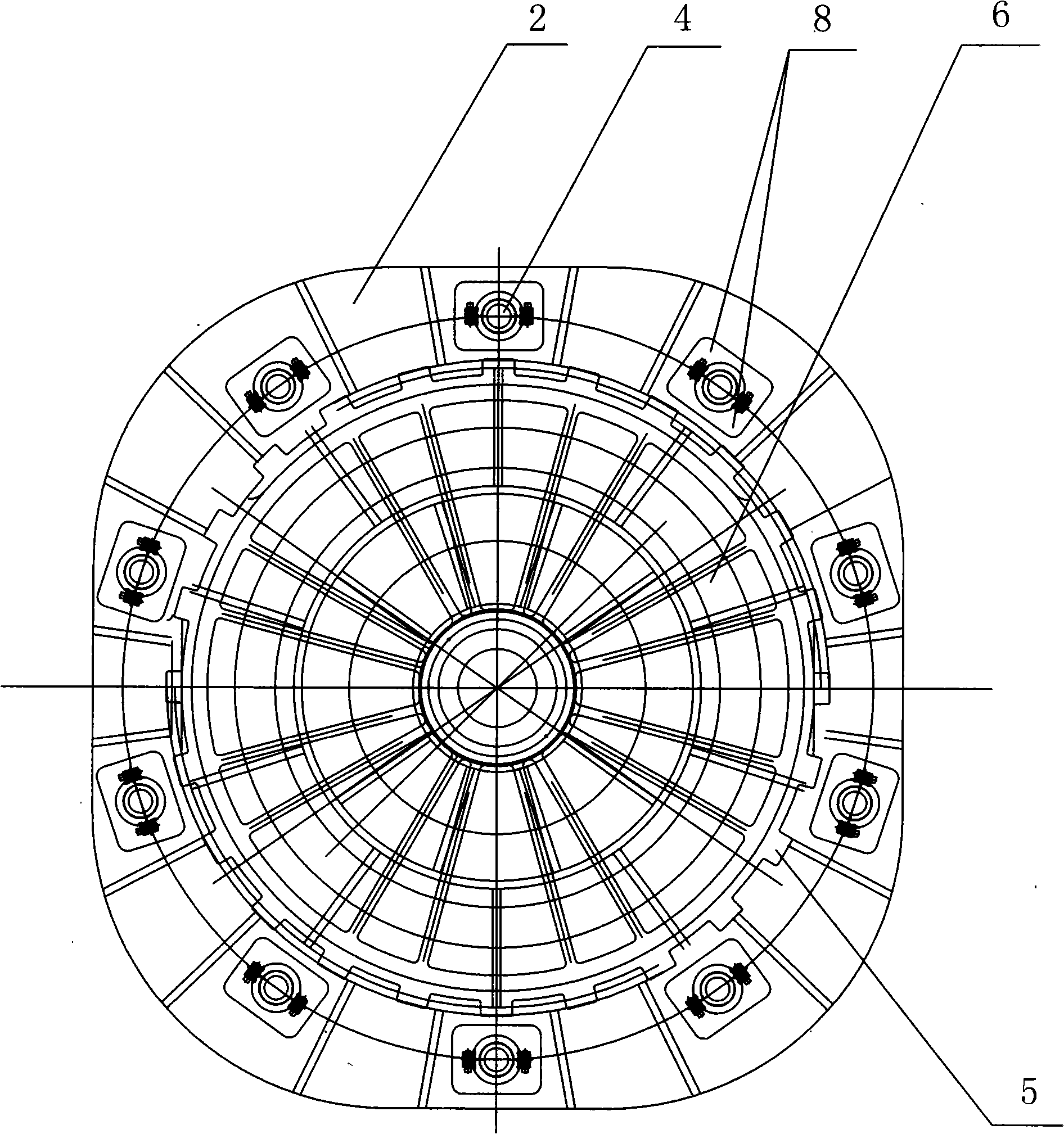
[0026] The column pressurized hydraulic vulcanizer of the present invention comprises a base 2, a vulcanization chamber 3, a gear ring 5, a beam cover 6, an afterburner cylinder 1, a column 4, an afterburner cylinder 1, a mold 7 and two half rings 8.

[0027] Figure 1, figure 2 As shown, 10 columns 4 are evenly distributed around the vulcanization chamber 3 in a circular equidistant manner. The upper end of the column 4 is fixed to the staggered ring 5 through two half-rings 8, and the lower end of the column 4 is connected to the piston rod of the booster cylinder 1. 10 The cylinder body of the booster cylinder 1 is fixed on the base 2, and its position corresponds to 10 columns 4, and each booster cylinder 1 can pressurize each column 4 separately.

[0028] As shown in Figure 1, above the base 2 is the vulcanization chamber 3. After the cross beam cover 6 is covered, turn the gear ring 5, and the teeth of the gear ring 5 will be engaged with the teeth of the beam cover 6 to ...


PUM


Abstract

The invention discloses a vertical-column pressurized hydraulic vulcanizing machine, comprising a base, a vulcanizing chamber, a crossbeam cover, a staggered tooth ring and a hydraulic clamping mechanism which provides a clamping force to a die; wherein the hydraulic clamping mechanism comprises vertical columns and a stressing oil cylinder which applies pressure to each vertical column; the vertical columns are uniformly arranged around the vulcanizing chamber in a ring shape; the stressing oil cylinder is uniformly arranged on the base in a ring shape; the upper end of the vertical column is connected with the staggered tooth ring and the lower end thereof is connected with the piston rod of the stressing oil cylinder; and the base, the vulcanizing chamber, the die, the crossbeam cover, the staggered tooth ring, the stressing oil cylinder and the vertical column form a closed force system. The force applied to each vertical column only corresponds to the pressure of the system; the uniformly distributed vertical columns can provide more uniform clamping force for the die, thus improving the quality of the tyre. All bearing parts of the vulcanizing machine can be dismounted, thus reducing the monomer transportation volume and creating conditions for producing the vulcanizing machine of larger specifications.

Description

(1) Technical field: [0001] The invention relates to tire manufacturing equipment, in particular to a column pressurized hydraulic vulcanizer. (two) background technology: [0002] For giant tires, the traditional process adopts vulcanization tank vulcanization and pressurized hydraulic vulcanization machine vulcanization. Due to the structure itself, the vulcanization tank vulcanization has low work efficiency and high labor intensity, and the vulcanized tires are difficult to meet the quality requirements of radial tires. [0003] The booster hydraulic mechanism of the existing pressurized hydraulic vulcanizer is that the booster cylinder installed on the base pushes the lower supporting plate upwards to apply a certain force to the lower mold, so as to provide the mold with the clamping force required for vulcanizing the tire. [0004] The disadvantages of this structure are: [0005] 1. When the booster cylinder is boosted, it not only needs to provide the clamping forc...

Claims


Application Information

Patent Timeline
Patent Type & Authority Applications(China)
IPC IPC(8): B29C35/02
Inventor 欧哲学李立苗张世东范世强陈原佳赵兴军李四平李尚起吴诗清姚华娟
Owner 桂林中昊力创机电设备有限公司
Features
  • R&D
  • Intellectual Property
  • Life Sciences
  • Materials
  • Tech Scout
  • Unparalleled Data Quality
  • Higher Quality Content
  • 60% Fewer Hallucinations
Learn More