
Piezoelectric fan driving device

Inactive Publication Date: 2018-08-23
LEE HAO
View PDF2 Cites 0 Cited by
  • Summary
  • Abstract
  • Description
  • Claims
  • Application Information

AI Technical Summary

Benefits of technology

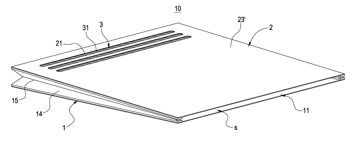
The present invention provides a piezoelectric fan driving device with a through hole on the membrane or piezoelectric sheet of a piezoelectric element. This allows for smooth cooling air to flow into the device and hot air to flow out. This prevents the cold air from mixing with the hot air in the device, which improves the device's dissipation.

Problems solved by technology

However, with mobile device such as smartphone and tablet computer pursuing thin type and high-effect, the effect of traditional heat pipes, uniform temperature plates or the rotating fans are not enough.
However, the above-mentioned piezoelectric type radiator has the disadvantage as follow.
Because the piezoelectric type radiator sucks a cold air from outside and exhausts hot air through the same opening, the cold air and the hot air are easily mixing in the cavity so that the hot air cannot completely be exhausted out of the cavity and the cold air cannot flow into the cavity smoothly, and thus lowering the cooling efficiency of the piezoelectric type radiator.
Also, as the traditional piezoelectric type radiator integrated with an electronic device, the piezoelectric element may need an AC power to drive and produce vibration.
Because most of the electronic devices only provide a DC power, and the DC power cannot drive the piezoelectric element, it is required to provide an additional device for producing a driving signal to drive the piezoelectric element, and thus the problem of integrated design of the electronic device and piezoelectric heat radiator is produced.

Method used


Image

  • Piezoelectric fan driving device
  • Piezoelectric fan driving device
  • Piezoelectric fan driving device

Examples


Embodiment Construction

[0022]The features of the invention believed to be novel are set forth with particularity in the appended claims. The invention itself, however, may be best understood by reference to the following detailed description of the invention, which describes exemplary embodiments of the invention, taken in conjunction with the accompanying drawings.

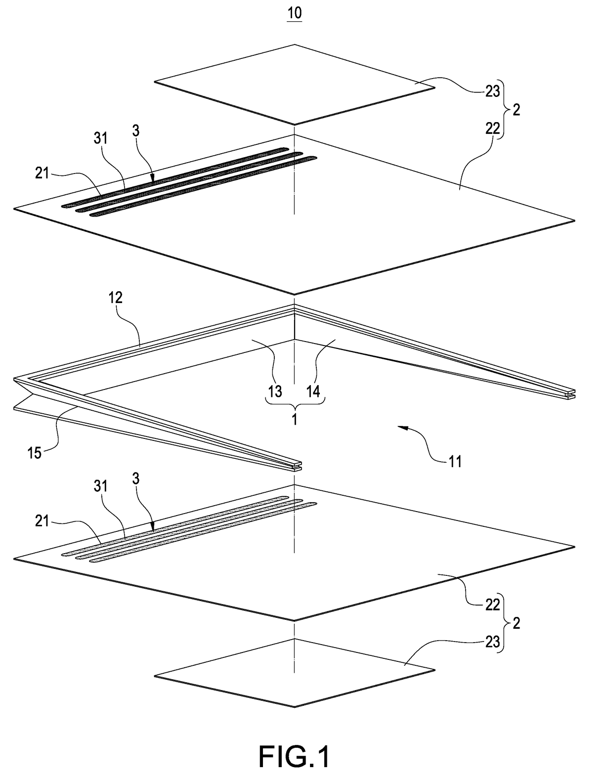
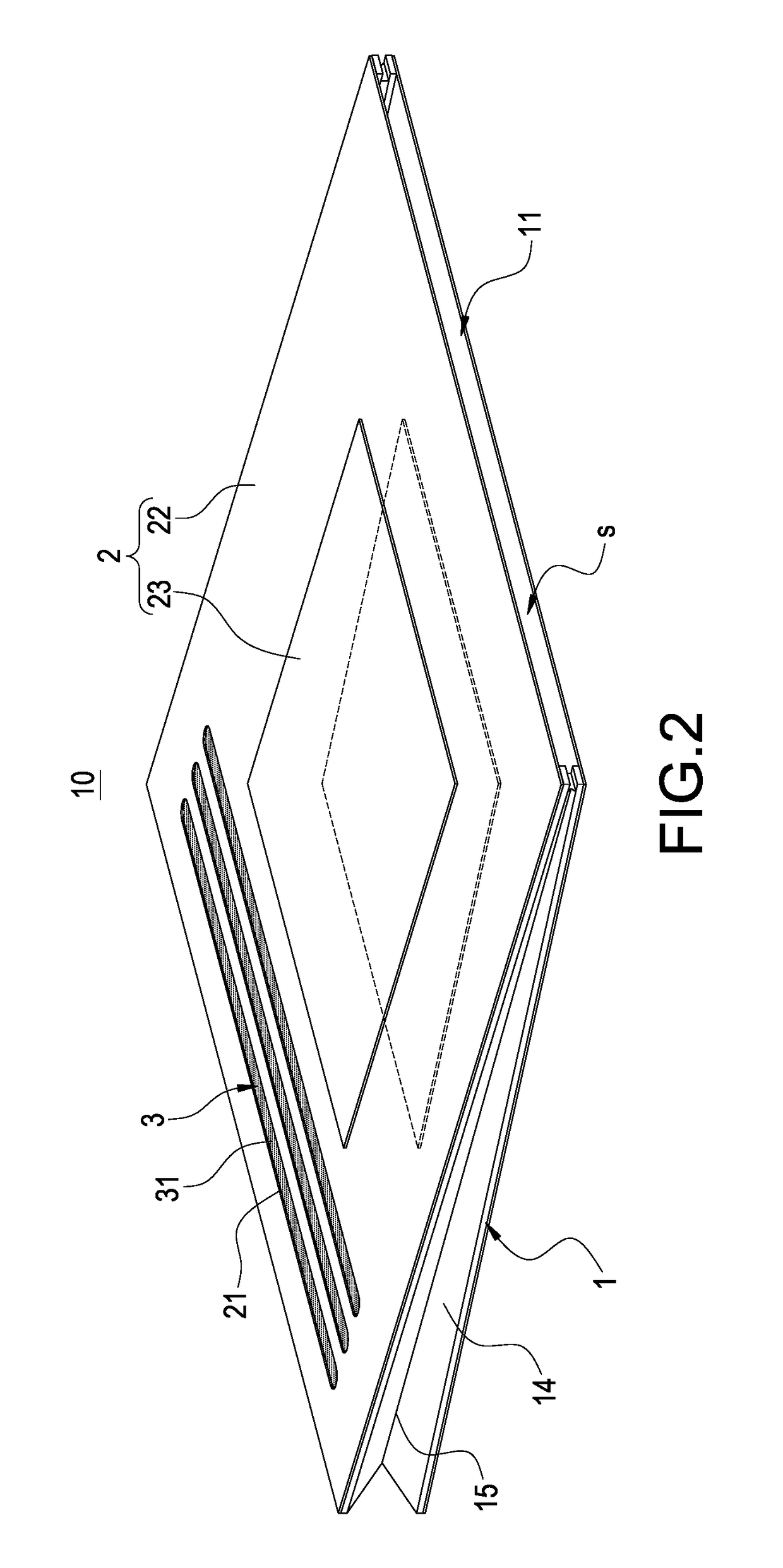
[0023]FIG. 1 shows an exploded view of a piezoelectric fan driving device of a first embodiment of the invention. FIG. 2 shows an assembly view of a piezoelectric fan driving device of a first embodiment of the invention. FIG. 3 shows a circuit block diagram of a piezoelectric fan driving device of a first embodiment of the invention. As shown in FIG. 3, a piezoelectric fan driving device of a first embodiment includes a piezoelectric fan 10 and a driving unit 20, wherein a DC power is inputted into the driving unit 20, and the DC power is converted into AC power to drive the piezoelectric fan 10.

[0024]The piezoelectric fan 10 includes a connec...


PUM


Abstract

The invention relates to a piezoelectric fan driving device comprising: a piezoelectric fan and a driving unit, wherein the piezoelectric fan comprises a connecting piece, two piezoelectric elements and at least one one-way air flowing piece. The connecting piece has an opening and two end surfaces. The two piezoelectric elements are fixed on the two end surfaces, and the connecting piece and two piezoelectric elements surround to form a cavity, one of the two piezoelectric elements having a through hole connecting to the cavity. The one-way air flowing piece connects the through hole. The driving unit electrically connects with the two piezoelectric elements to convert a DC power to an AC power, and the two piezoelectric elements are driven by the AC power.

Description

BACKGROUND OF THE INVENTIONField of the Invention[0001]The invention relates to a driving device, particularly a piezoelectric fan driving device which is used to drive a piezoelectric fan by converting DC power into AC power.Description of the Related Art[0002]In recent years, due to the rapid development of electronic products, the function of electronic components becomes more powerful, and the size of electronic components is gradually reduced and thus heat produced from an electronic component per unit area becomes more and more. Traditional thermal dissipation solution is the use of heat pipes matching the cooling fins or uniform temperature plate, or cooling fins matching the rotating fan to exhaust heat to outside for the purpose of cooling.[0003]However, with mobile device such as smartphone and tablet computer pursuing thin type and high-effect, the effect of traditional heat pipes, uniform temperature plates or the rotating fans are not enough. Therefore, a new piezoelect...

Claims


Application Information

Patent Timeline
IPC IPC(8): F04B45/04F04B45/047F04B53/10H02N2/06
CPCF04B45/041H02N2/06F04B53/10F04B45/047F04B45/027F04B53/102F04B53/1037
Inventor LEE, HAO
Owner LEE HAO
Learn More