Electronic apparatus and method of controlling power supply

a technology of electronic equipment and power supply, applied in the field of electronic equipment and a control method of power supply, can solve the problems of difficult to detect a difference in the attachment state not necessarily a satisfactory solution, etc., and achieve the effect of reducing the power consumption of wearable optical devices

Active Publication Date: 2018-08-23
SONY CORP
View PDF2 Cites 1 Cited by
  • Summary
  • Abstract
  • Description
  • Claims
  • Application Information

AI Technical Summary

Benefits of technology

[0012]According to the embodiments of the present disclosure, the power consumption of the wearable optical device can be reduced effectively by determining whether the wearable optical device is usable.
[0013]Note that the

Problems solved by technology

Although the technique disclosed in Patent Literature 2 as an example can reduce power consumption of the wearable optical device, this is not necessarily a satisfactory so

Method used


Image

  • Electronic apparatus and method of controlling power supply
  • Electronic apparatus and method of controlling power supply
  • Electronic apparatus and method of controlling power supply

Examples


first embodiment

1. FIRST EMBODIMENT

(1-1. System Configuration)

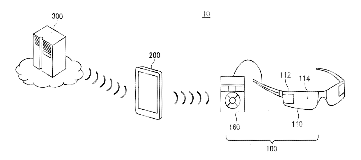
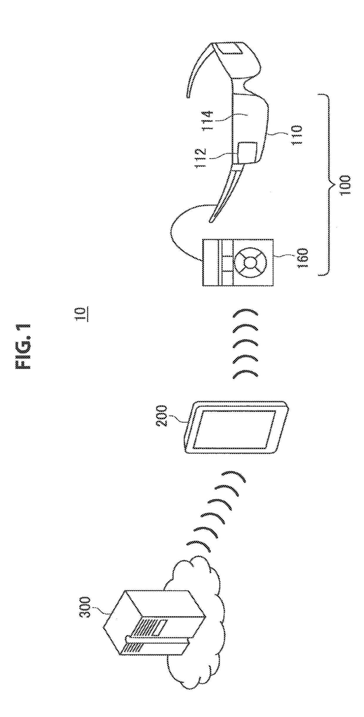
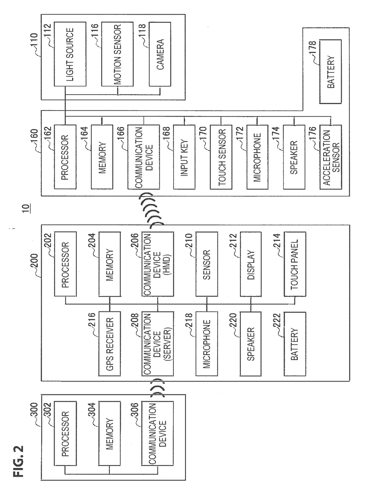
[0034]FIG. 1 is a diagram showing a schematic configuration of a system according to a first embodiment of the present disclosure. FIG. 2 is a block diagram showing a schematic functional configuration of the system shown in FIG. 1. Referring to FIGS. 1 and 2, the system 10 includes a head-mounted display (HMD) 100, a smartphone 200, and a server 300. Hereinbelow, configurations of the respective devices will be described.

(Head-Mounted Display)

[0035]The HMD 100 includes a display unit 110 and a control unit 160. The display unit 110 has a housing in the shape of, for example, glasses, and is worn by a user (observer) on his or her head. The control unit 160 is connected to the display unit 110 by a cable.

[0036]The display unit 110 is provided with a light source 112 and a light guide plate 114 as shown in FIG. 1. The light source 112 emits image display light according to control of the control unit 160. The light guide plate 114 guides ...

second embodiment

2. SECOND EMBODIMENT

[0086]A second embodiment of the present disclosure will be described. In the second embodiment, the state of the display unit 110 is determined using a method that is different from the first embodiment in a system 10 similar to the first embodiment. Thus, for the configuration of the system that is common to the first embodiment, repeated description will be omitted, and in particular, a process for the state determination will be described.

[0087]FIG. 9 is a schematic block diagram showing a functional configuration of the system according to the second embodiment of the present disclosure. Referring to FIG. 9, in a system 20 according to the present embodiment, a display unit 110 of an HMD 100 is provided with a switch 120 that is configured to detect the state of a connection part of an attachment member, in addition to functional components similar to the system 10 described above. This switch 120 will be described below with reference to FIG. 10.

[0088]FIG. ...

third embodiment

3. THIRD EMBODIMENT

[0099]A third embodiment of the present disclosure will be described. In the third embodiment, the state of the display unit 110 is determined using a method that is different from the first embodiment in a system 10 similar to the first embodiment. Thus, for the configuration of the system that is common to the first embodiment, repeated description will be omitted, and in particular, a process for the state determination will be described.

[0100]FIG. 13 is a schematic block diagram showing a functional configuration of the system according to the third embodiment of the present disclosure. Referring to FIG. 13, in a system 30 according to the present embodiment, a display unit 110 of an HMD 100 is provided with an illuminance sensor 130, in addition to functional components similar to the system 10 (or system 20) described above. The illuminance sensor 130 is an example of a state detection unit used to detect an environmental condition surrounding the wearable o...


PUM


Abstract

[Object] To effectively reduce power consumption of a wearable optical device by determining whether the wearable optical device is usable.
[Solution] Provided is an electronic apparatus including a wearable optical device, a state detection unit configured to detect a state relating to the wearable optical device, a state determination unit configured to determine that the detected state is at least one of a first state in which the wearable optical device is worn by a user in usable state or a second state in which the wearable optical device is worn or carried by the user in unusable state, and a power supply controller configured to control a power supply state of the electronic apparatus based on a result obtained by the determination.

Description

CROSS REFERENCE TO RELATED APPLICATIONS[0001]The present application is a continuation application of U.S. patent application Ser. No. 15 / 118,597, filed Aug. 16, 2016, which is a National Stage Entry of PCT / JP2014 / 081727, filed Dec. 1, 2014, and claims the benefit of priority from prior Japanese Patent Application 2014-031606, filed Feb. 21, 2014, the entire content of which is hereby incorporated by reference.TECHNICAL FIELD[0002]The present disclosure relates to an electronic apparatus and a method of controlling power supply.BACKGROUND ART[0003]A various types of optical devices allowing a viewer to perceive a virtual image superimposed on an image in real space have been recently developed. An example of such optical devices includes a wearable optical device, and in particular, a device that is worn by the user on the head is known as a head-mounted display (HMD). An exemplary type of the HMD is known in which a half mirror serving as a display surface is provided in front of t...

Claims


Application Information

Patent Timeline
IPC IPC(8): G06F1/32G02B27/00H04N5/74G06F1/16G02B27/01G06T19/00G09G5/10
CPCY02D50/20G06F1/163Y02D10/128G09G2340/0407G09G2330/021G02B27/0093G02B27/017G06F1/3218G06T19/006G09G5/10G09G2320/0626H04N5/74G02B2027/0178G06F2200/1637G06F1/3265G06F1/325G06F1/3237G06F1/3206G06F1/1694Y02D10/153G02B2027/0183G02B2027/0138Y02D10/00Y02D30/50
Inventor ISHIKAWA, HIROTAKAIWATSU, TAKESHITSUKAHARA, TSUBASA
Owner SONY CORP
Why Eureka
Try Eureka