
Battery, particularly a button cell, and method for manufacture of such a battery

a button cell and battery technology, applied in the field of button cell manufacturing, can solve the problems of occupying a significant amount of space, limiting the active volume of the battery, and occupying a large space, and achieve the effect of avoiding contamination of the bonding surface and without any risk of degrading

Active Publication Date: 2018-08-23
THE SWATCH GRP RES & DEVELONMENT LTD
View PDF2 Cites 5 Cited by
  • Summary
  • Abstract
  • Description
  • Claims
  • Application Information

AI Technical Summary

Benefits of technology

The present invention proposes a new method for manufacturing batteries that increases the active volume and improves the properties of the battery's bonded assembly. The method involves a two-phase assembly process. In the first phase, the two parts of the battery are bonded with an adhesive joint to form a structure with an electrically isolated adhesive joint. The active material is then added to fill the structure. In the second phase, the structure is closed by welding the third part to the bonded parts. The key feature of the method is that the adhesive joint is designed to withstand internal pressure in the battery. This allows for the use of an adhesive that is mechanically and chemically resistant and helps to maintain the purity of the bonding surfaces. The manufacturing method is efficient and reliable.

Problems solved by technology

This assembly with a preformed crimped seal has the drawback of occupying a significant amount of space which will restrict the active volume of the battery.
To reduce the space allocated to the sealing junction, an adhesive joint instead of the preformed elastomer seal is a promising solution, but which raises some technical issues.
Thus, it is recommended not to go beyond 70° C., which limits the opportunity to choose the most suitable adhesive for ensuring the best mechanical and chemical resistance of the assembly.

Method used

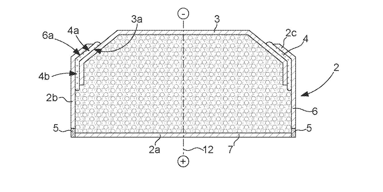

Image

  • Battery, particularly a button cell, and method for manufacture of such a battery
  • Battery, particularly a button cell, and method for manufacture of such a battery
  • Battery, particularly a button cell, and method for manufacture of such a battery

Examples


Embodiment Construction

[0019]The present invention relates to a method for manufacturing a battery, in particular a button cell battery, which is assembled by bonding and welding starting with at least three parts.

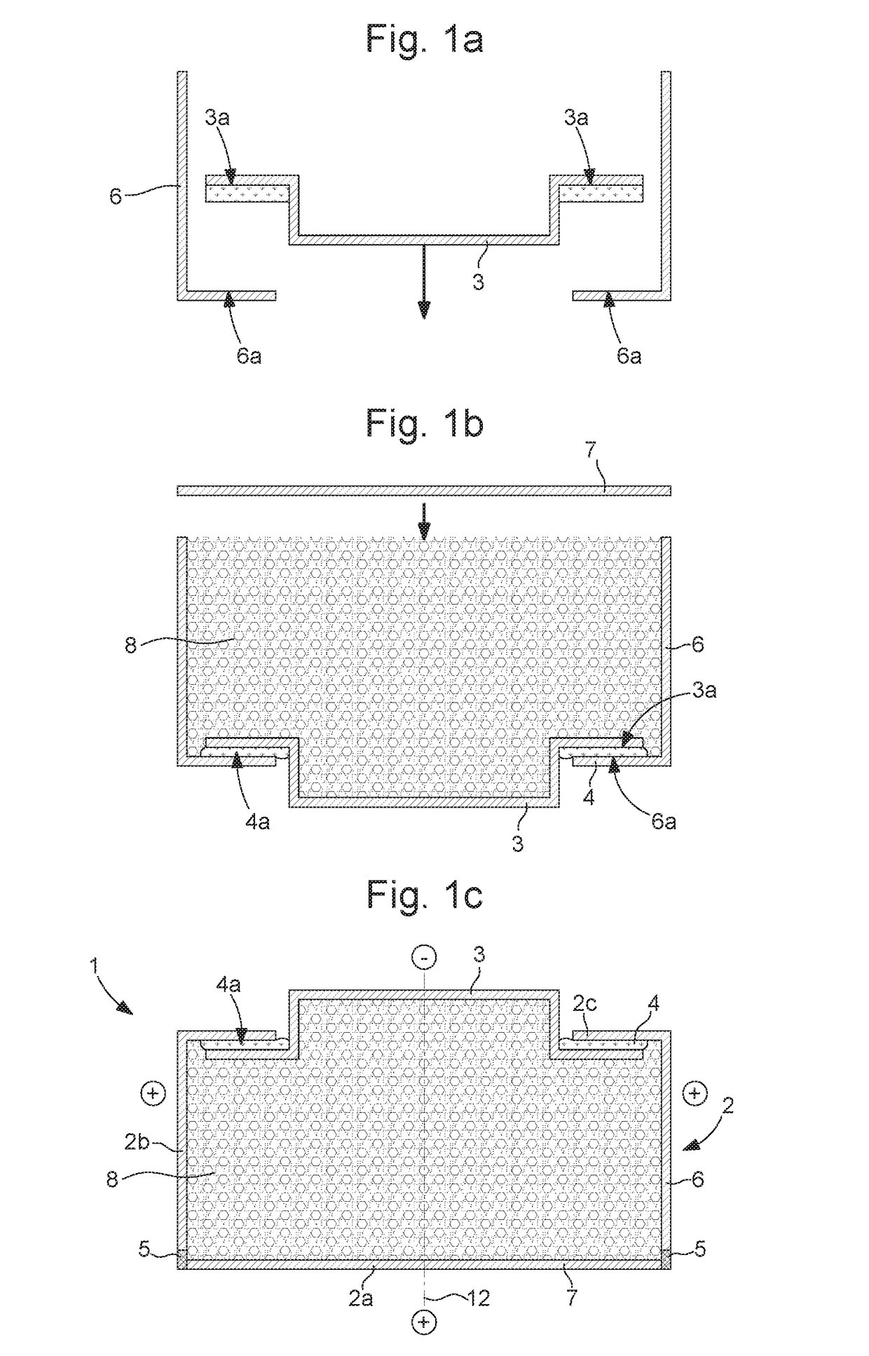
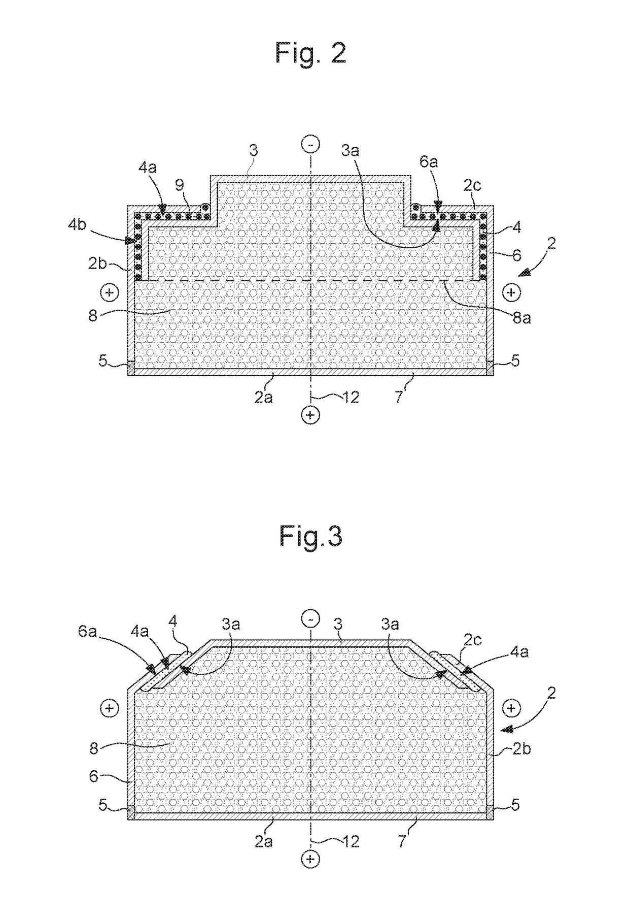
[0020]As illustrated in FIG. 1c, amongst others, the button cell, obtained from this manufacturing method, includes a metal casing 1 formed of a cup 2, defining the positive pole of the battery, and a closure part 3 defining the negative pole of the battery and closing the cup. According to the invention, the connection between the closure part and the cup is provided by an adhesive joint 4, and the connection between at least two parts forming the cup is provided by a weld or solder 5, with or without the addition of material, which is called hereafter the “welded joint”. Also according to the invention, the adhesive joint is disposed on an inner face of cup 2 and the welded joint may be positioned at different places on the cup. For example, it may be positioned at the junction between the bot...


PUM


Abstract

The present invention relates to a method for manufacturing a battery comprising a casing provided with a cup and a closure part for said cup, the method comprising the successive steps consisting in:providing at least three parts with a first part defining one pole, and a second part and a third part defining the other pole and intended to form together the cup, the first and second parts respectively comprising a first surface and a second surface (6a) of matching shape, at least one adhesive portion of each of said surfaces extending in a geometric surface non-parallel to the general axis of the battery;bonding the aforementioned first and second surfaces to provide a structure with an adhesive joint between the first and second parts;welding the third part to the second part;the adhesive joint being arranged against an inner face of the cup, the aforementioned adhesive portion of the second part forming a stop, along the general axis, for the first part, which is located inside the cup.

Description

[0001]This application claims priority from European Patent Application No. 17157252.2 filed on Feb. 21, 2017, the entire disclosure of which is hereby incorporated herein by reference.FIELD OF THE INVENTION[0002]The present invention relates to a method for manufacturing batteries and, in particular, button cells. It also relates to the battery obtained by the aforementioned manufacturing method.BACKGROUND OF THE INVENTION[0003]Button cell batteries generally include a casing provided with a cup and a lid respectively forming the positive and negative poles of the battery. Conventionally, button cell batteries are sealed with a preformed elastomer seal which is positioned between the cup and the lid. This elastomer seal provides galvanic isolation between the poles and forms a barrier between the electrolyte contained inside the battery and the external environment. Such an assembly is disclosed, for example, in GB Patent No 1566061.[0004]This assembly with a preformed crimped seal...

Claims


Application Information

Patent Timeline
IPC IPC(8): H01M2/02
CPCH01M2/0222H01M50/109H01M50/153Y02E60/10H01M50/545H01M50/169Y02P70/50H01M50/56
Inventor VUILLE, PIERRYERDEMLI, FRANCOISHAERING, PASCALYILDIZ, BURHAN
Owner THE SWATCH GRP RES & DEVELONMENT LTD
Learn More