Wireless power transfer system and driving method therefor

a power transfer system and wireless technology, applied in the direction of transmission, transportation and packaging, circuit monitoring/indication, etc., can solve the problems of power loss, short circuit, and battery of electronic devices that are not charged, so as to prevent unnecessary power waste and remove risks.

Inactive Publication Date: 2018-08-23
LG INNOTEK CO LTD
View PDF1 Cites 13 Cited by
  • Summary
  • Abstract
  • Description
  • Claims
  • Application Information

AI Technical Summary

Benefits of technology

[0030]According to an embodiment, even if a power transfer unit does not receive a separate message from a power receiver unit, it is possible to sense that a battery of the power receiver unit has been fully charged. Accordingly, it is possible to remove a risk due to non-reception of a message between the power transfer unit and the power reception unit. Further, when the power transfer unit receives a full charge message after the power receiver unit is fully charged, it is possible to prevent unnecessary waste of power between the units. Further, since the power transfer unit determines whether to stop wireless power transfer by determining by itself the charge state of a load, it is possible to a loss of power and heat generation due to non-recognition of full charge completion of the battery.

Problems solved by technology

However, since the contact terminals of electronic device are exposed to the outside, they may be contaminated by dirt or a short circuit may occur due to humidity.
In these cases, there is a problem that the batteries of electronic devices are not charged due to poor contact between a contact terminal and a charger.
When the battery of a receiver is fully charged, a transmitter does not recognize this fact and keeps transferring power, so power is lost and the temperature of the transmitter and receiver is increased due to heat generation thereof.

Method used


Image

  • Wireless power transfer system and driving method therefor
  • Wireless power transfer system and driving method therefor
  • Wireless power transfer system and driving method therefor

Examples


Embodiment Construction

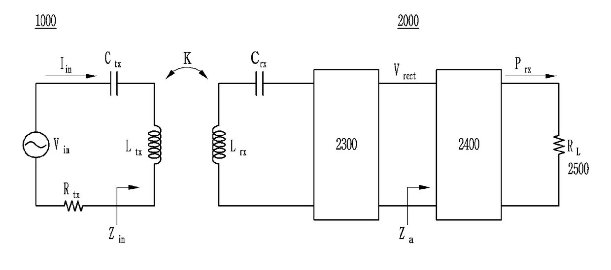
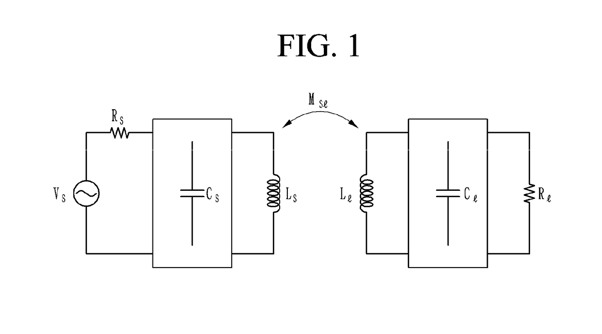
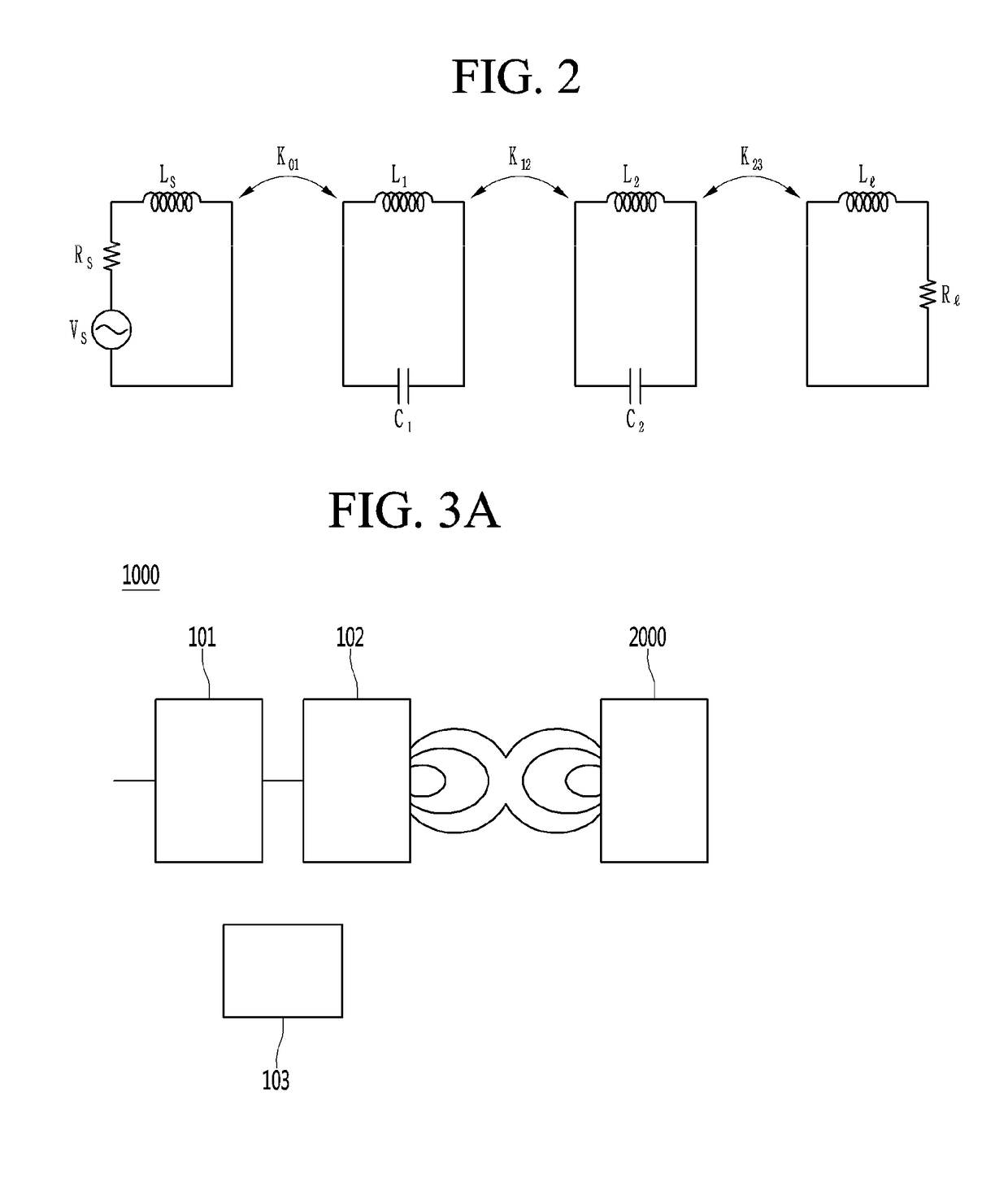
[0042]A wireless power transfer system including a power transfer unit having a function of wirelessly transmitting power and a power receiver unit wirelessly receiving power according to an embodiment of the present invention is described hereafter in detail with reference to the drawings. Embodiments to be described hereafter are provided as examples for sufficiently communicating the spirit of the present invention to those skilled in the art. Accordingly, the present invention is not limited to the following embodiments and may be implemented by other ways. The sizes, thicknesses, etc. of devices may be exaggerated for convenience in the drawings. The like reference numerals indicate substantially the like components throughout the specification.

[0043]Embodiments may include a communication system that selectively uses various frequency bands from a low frequency (50 kHz) to a high frequency (15 MHz) to wirelessly transfer power and can exchange data and control signals for syst...


PUM


Abstract

The present invention provides a method of driving a power transfer unit wirelessly transferring power, the method including: detecting a voltage and a current of the power transfer unit; detecting a change in the voltage and the current; and sensing that a battery receiving wireless power from the power transfer unit is being fully charged on the basis of the change in the voltage and the current.

Description

TECHNICAL FIELD[0001]The present invention relates to a wireless power transfer system and a method of driving the wireless power transfer system.BACKGROUND ART[0002]In general, various electronic devices are equipped with a battery and use the power stored in the battery. The batteries of electronic devices can be replaced and can also be recharged. To this end, electronic devices have a contact terminal for connecting an external charger. That is, electronic devices are electrically connected with a charger through the contact terminal. However, since the contact terminals of electronic device are exposed to the outside, they may be contaminated by dirt or a short circuit may occur due to humidity. In these cases, there is a problem that the batteries of electronic devices are not charged due to poor contact between a contact terminal and a charger.[0003]In order to solve this problem, wire power transfer (WPT) has been proposed to wirelessly charge electronic devices.[0004]Wirele...

Claims


Application Information

Patent Timeline
Patent Type & Authority Applications(United States)
IPC IPC(8): H02J7/00H02J7/02H02J50/12H02J50/80
CPCH02J7/007H02J7/025H02J50/12H02J50/80H04B5/0037H04B5/0081H02J7/0049H02J7/00712
Inventor BAE, SU HO
Owner LG INNOTEK CO LTD
Why Eureka
Try Eureka