Method and device for determining features of error correcting code system

a technology of error correction and code system, applied in the field of method for determining features of error correction code system, can solve the problems of high transmission loss in air and solid materials, complex design of error correction code adapted to bf channel in the context of millimeter wave based communication, and inability to travel on few kilometers for signals based on millimeter wave communication technologies, etc., to achieve low complexity algorithm, accurate and evaluated design rate, and minimize outage probability

Active Publication Date: 2018-08-23
MITSUBISHI ELECTRIC CORP
View PDF3 Cites 5 Cited by
  • Summary
  • Abstract
  • Description
  • Claims
  • Application Information

AI Technical Summary

Benefits of technology

[0037]Thus, the design rates are accurate and evaluated with a low complexity algorithm.
[0038]In an embodiment, the statistical method is implemented offline and allows obtaining a table, called correspondence table, comprising, for each value of the parameter comprised in the pre-defined set of values of the parameter and for each probability distribution set of the pre-defined plurality of probability distribution sets, the features of the error correcting code syst...

Problems solved by technology

However, while signals using lower frequency bands, such as GSM (Global System for Mobile Communications), can propagate on a high distance and easily penetrate buildings, a signal based on millimeter wave communication technologies can only travel on few kilometers, and suffers from high transmission losses in the air and solid materials.
However, designing a single error correcting code adapted to BF channels in the context of millimeter wave based communications is complex.
However, using independent parallel error correcting codes on BF c...

Method used


Image

  • Method and device for determining features of error correcting code system
  • Method and device for determining features of error correcting code system
  • Method and device for determining features of error correcting code system

Examples


Embodiment Construction

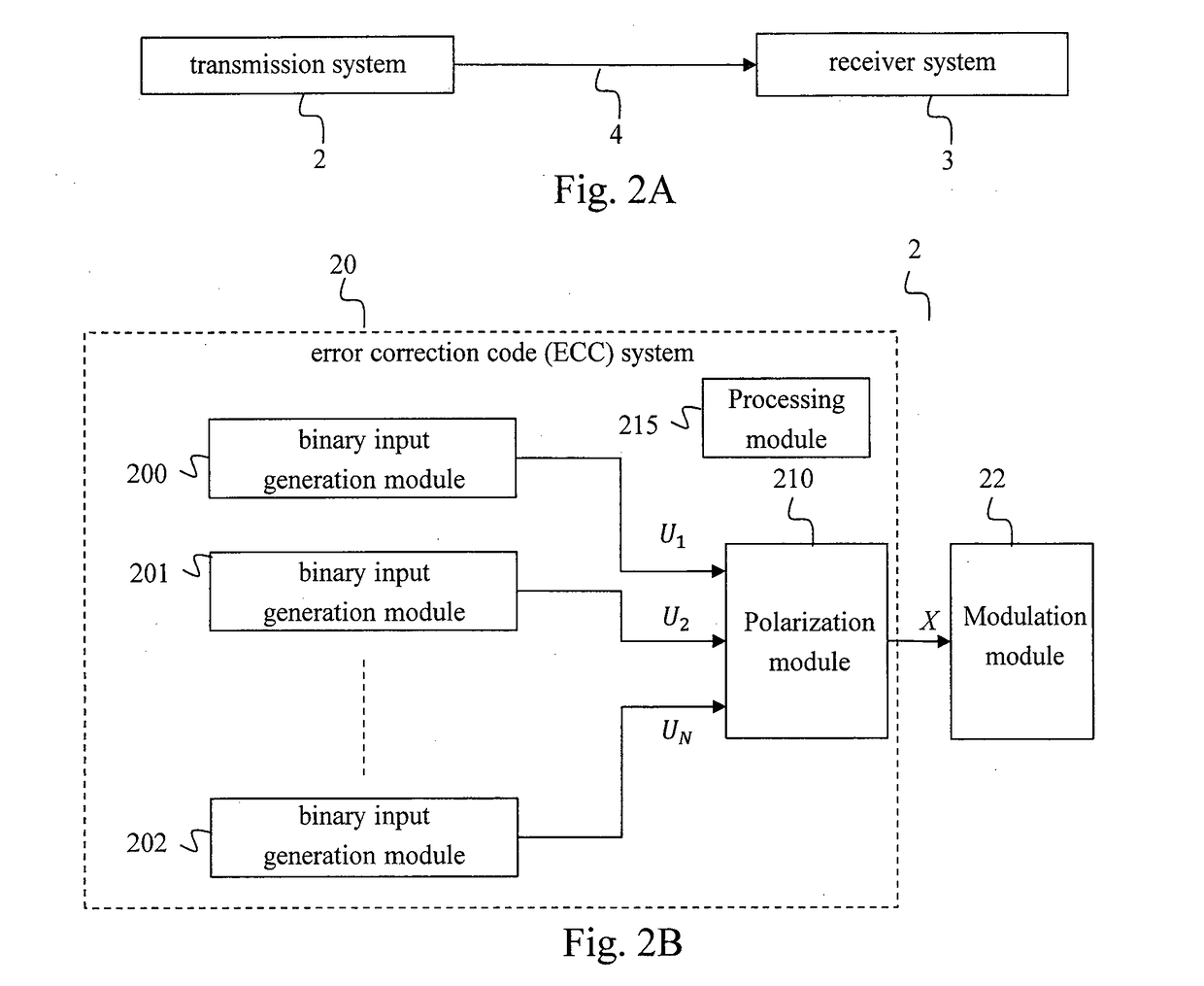
[0061]FIG. 2A illustrates schematically an example of a communication system in which the invention can be implemented.

[0062]The communication system 1 comprises a transmission system 2 and a receiver system 3 communicating using a wireless channel 4 based on a millimeter wave technology using, for instance, the “60” GHz radio band. Bitrates allowed by the system 1 are, for example, of the order of few GBits / s.

[0063]FIG. 2B illustrates schematically an example of transmission system adapted to implement the invention.

[0064]The transmission system 2 comprises an error correction code (ECC) system 20 and a modulation module 22. The ECC system 20 comprises a number N (N≥2) of binary input generation modules 200-202, a polarization module 210 and a processing module 215. Each binary input generation module 200-202 provides a component of a binary input vector U=[U1, . . . , UN] to the polarization module 210. Each binary input generation module 200-202 comprises an ECC encoding module, ...


PUM


Abstract

A method for determining features of an error correcting code system, comprising independent error correcting codes and a polarization module, allowing transmitting a binary input vector on block fading sub-channels, the independent error correcting codes generating components of the binary input vector and a channel polarization being applied to the binary input vector by the polarization module. The method comprises: obtaining characteristics of the block fading sub-channels; and, determining features of said error correcting code system, comprising, for each error correcting code, a rate of said error correcting code, adapted to the obtained characteristics and minimizing a function of a probability that an instantaneous equivalent channel capacity of the block fading sub-channels is below a transmission rate transmitted on the block fading sub-channels.

Description

TECHNICAL FIELD[0001]The invention concerns a method for determining features of an error correcting code system, and a device implementing the method.BACKGROUND ART[0002]Even though data storage technologies and communication technologies are improving, the quantity of data to store or to communicate is increasing in parallel. As a consequence, research for high data rate communication and storage technologies are still active. Millimeter wave technologies is one research focus in the field of high data rate communications.[0003]Millimeter wave communication technology uses frequencies going from “30” to “300” GHz with wavelengths from “10” to “1” mm. Millimeter wave communication technology allows attaining data rates up to few tens of Gbits / s. However, while signals using lower frequency bands, such as GSM (Global System for Mobile Communications), can propagate on a high distance and easily penetrate buildings, a signal based on millimeter wave communication technologies can onl...

Claims


Application Information

Patent Timeline
IPC IPC(8): H03M13/11H03M13/13H04L1/00H03M13/29
CPCH03M13/1111H03M13/13H04L1/0042H03M13/2957H03M13/033H03M13/1102
Inventor GRESSET, NICOLASEXPOSITO, VICTOR
Owner MITSUBISHI ELECTRIC CORP
Why Eureka
Try Eureka