Method and apparatus in ue and base station supporting narrowband communication
- Summary
- Abstract
- Description
- Claims
- Application Information
AI Technical Summary
Benefits of technology
Problems solved by technology
Method used
Image
Examples
embodiment 1
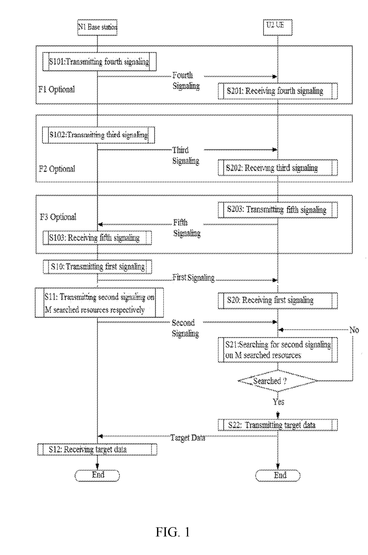
[0147]Embodiment 1 gives an example of a flowchart illustrating uplink data transmission, as shown in FIG. 1. In FIG. 1, the base station N1 is the maintenance base station of the serving cell of the UE U2, steps identified in boxes F1, F2 and F3 are optional steps.
[0148]The base station N1 transmits a first signaling in S10, transmits a second signaling on each of M searched resources respectively in S11 and receives a target data in S12.
[0149]The UE U2 receives the first signaling in S20 and searches for the second signaling on M searched resources in a current group in S21. If the second signaling is searched out, the UE U2 transmits the target data in S22; if the second signaling is not searched, the UE U2 continues searching for the second signaling on a next group of M searched resources.
[0150]In embodiment 1, the first signaling indicates a first time unit set, time units occupied by the M searched resources all belong to the first time unit set, the second signaling includes...
embodiment 2
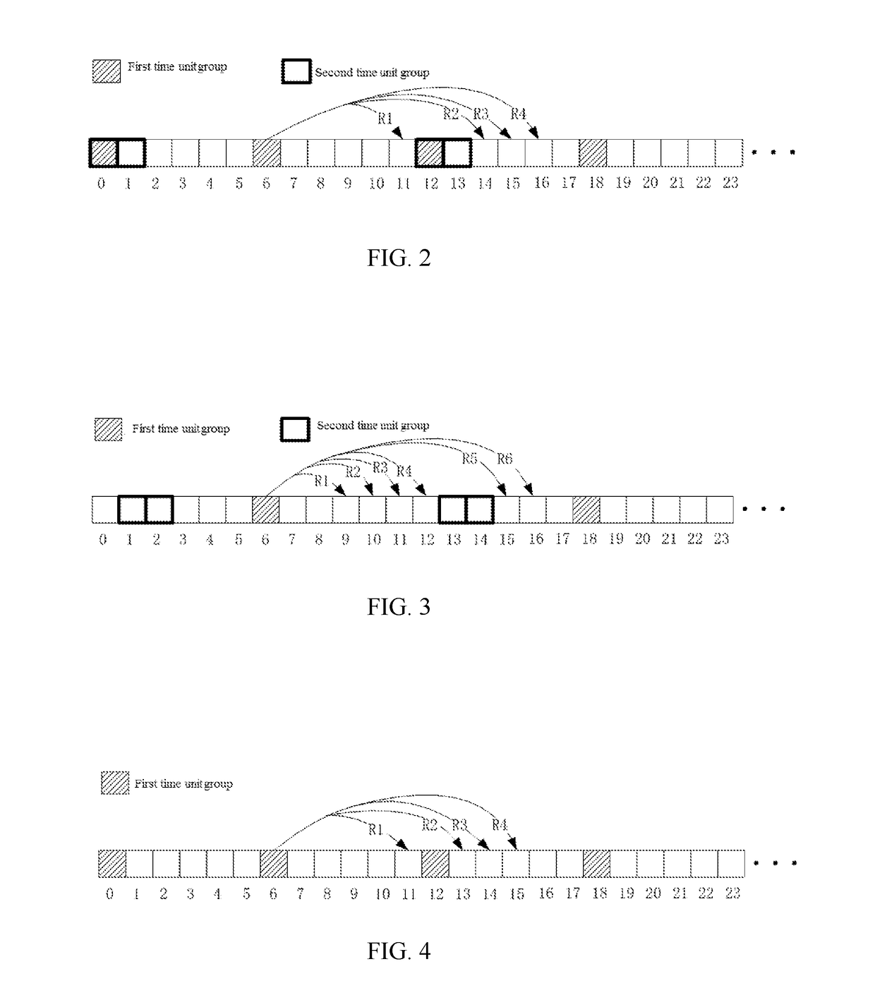
[0157]Embodiment 2 gives an example of a diagram illustrating a plurality of time unit groups having overlap, as shown in FIG. 2. In FIG. 2, time units {0, 1, 2, . . . , 23, . . . } are sorted in a chronological order and form a third time unit set. Squares marked by oblique lines indicate time units in the first time unit group, and squares marked by bold line frames indicate time units in the second time unit group.
[0158]The third signaling identifies J time unit groups that appear periodically in the third time unit set—the first time unit group and the second time unit group, the J is 2. The second time unit set is composed of the time units in the J time unit groups that appear periodically, which are cascaded in a chronological order, that is, including time units {0, 1, 6, 12, 13, 18, . . . }. The first time unit group is overlapped with a time unit in the second time unit group, for example, time units {0, 12, . . . }.
[0159]In another embodiment of Embodiment 2, the first ti...
embodiment 3
[0164]Embodiment 3 gives an example of a diagram illustrating a plurality of time unit groups having no overlap, as shown in FIG. 3. In FIG. 3, time units {0, 1, 2, . . . , 23, . . . } are sorted in a chronological order and form a third time unit set. Squares marked by oblique lines indicate time units in the first time unit group, and squares marked by bold line frames indicate time units in the second time unit group.
[0165]The third signaling identifies J time unit groups that appear periodically in the third time unit set—the first time unit group and the second time unit group, the J is 2. The second time unit set is composed of the time units in the J time unit groups that appear periodically, which are cascaded in a chronological order, that is, including time units {1, 2, 6, 13, 14, 18 . . . }. The first time unit group is not overlapped with the time unit in the second time unit group, the first time unit group includes time units {6, 18, . . . }, the second time unit group...
PUM
 Abstract
Description
Claims
Application Information
 - R&D
- Intellectual Property
- Life Sciences
- Materials
- Tech Scout
- Unparalleled Data Quality
- Higher Quality Content
- 60% Fewer Hallucinations
Browse by: Latest US Patents, China's latest patents, Technical Efficacy Thesaurus, Application Domain, Technology Topic, Popular Technical Reports.
© 2025 PatSnap. All rights reserved.Legal|Privacy policy|Modern Slavery Act Transparency Statement|Sitemap|About US| Contact US: help@patsnap.com


