Method for Removing Amine From a Contaminated Hydrocarbon Streams

a technology of hydrocarbon streams and amines, which is applied in the direction of gaseous fuels, separation processes, water treatment, etc., can solve the problems of low contamination removal rate, small environmental footprint, and small site requirements, so as to reduce any post-treatment costs and minimize capital costs

Active Publication Date: 2018-08-30
NEXOSOLUTIONS
View PDF2 Cites 0 Cited by
  • Summary
  • Abstract
  • Description
  • Claims
  • Application Information

AI Technical Summary

Benefits of technology

The patent describes a new system for removing mercaptans from water. This system is smaller and more efficient than existing methods, with a smaller environmental impact and the ability to be modular and flexible. The process also produces no waste, reducing costs and the need for secondary treatments. Overall, this system is a better solution for removing mercaptans from water.

Problems solved by technology

However, the mixing and separation steps in these processes are not very efficient, resulting in low contamination removal rates.
Furthermore, improvements to the extraction efficiency of such approaches often require using larger vessels, larger quantities of water and better pumping systems to handle such water, and larger system foundations, thus making the improvements cost inhibitive.
The novel system is an extractor-separator that is small in size leading to a small environmental footprint and smaller site requirements.

Method used


Image

  • Method for Removing Amine From a Contaminated Hydrocarbon Streams
  • Method for Removing Amine From a Contaminated Hydrocarbon Streams
  • Method for Removing Amine From a Contaminated Hydrocarbon Streams

Examples


example 1

[0073]The presently described extractor-separator system was used to remove sulfur-containing contaminants from a liquid hydrocarbon stream. The novel system and methods were designed to be flexible and usable with a variety of processing equipment, particularly those already established.

[0074]In the present example, a miniaturized extractor-separator system was assembled using the same treatment stages as a full-size extractor-separator system described above. FIG. 4 shows the schematics of the small-scale extractor-separator system, including the high-pressure injectors (403, 404) and injection points for the additive (401) and the water (402), in addition to the valve arrangement, the contactor (410) and extractor stages (411) and the effluent streams. Additions to the miniaturized extractor-separator system include sampling points to monitor the process.

[0075]A 1.65 GPM slipstream of liquid condensate was processed by the miniaturized extractor-separator system. This on-site tes...

example 2

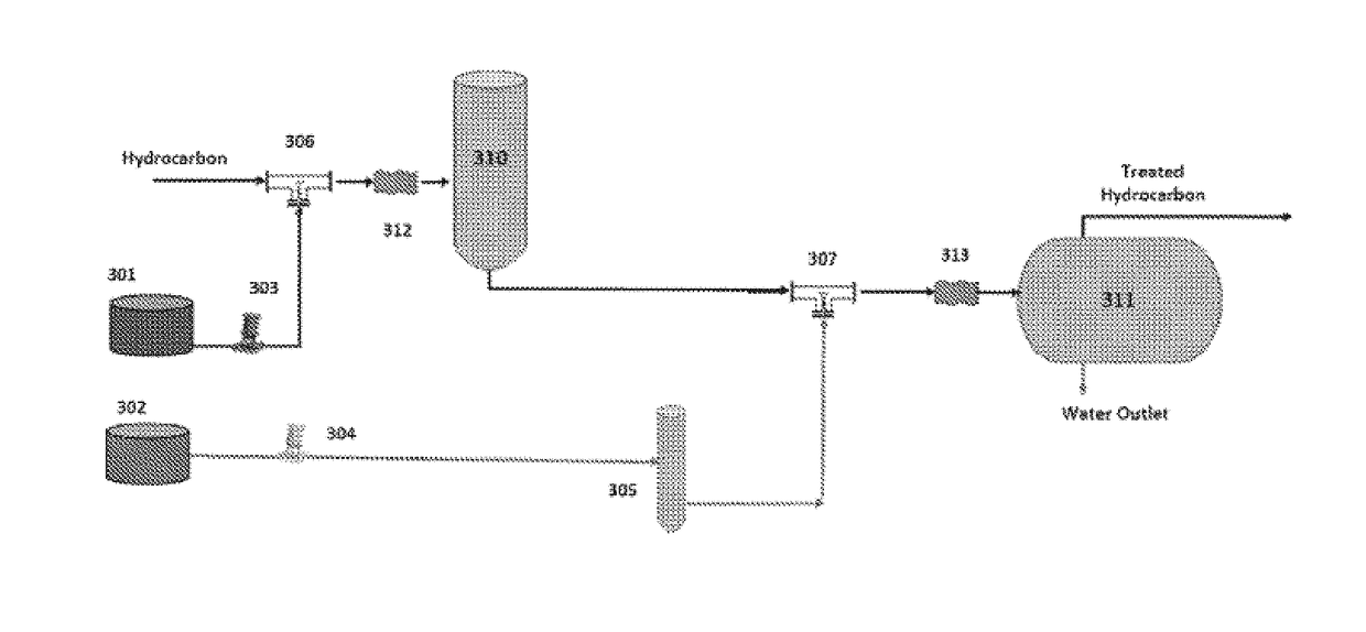
[0103]The presently described extractor-separator system can also recover amines from a treated liquid hydrocarbon stream. Amine recovery is slightly different from the sulfur-containing species in Example 1 in that a chemical additive is not needed to transform the amines into water-soluble compounds. Furthermore, this example demonstrates the flexibility of the extractor-separator system and its incorporation in an existing process.

[0104]In the present example, an existing amine gas treating system was modified to include the extractor-separator system. In an amine gas treatment, alkanolamines (commonly referred to simply as amines) are used to remove hydrogen sulfide (H2S) and carbon dioxide (CO2) from gases, typically liquid petroleum gas (LPG). Considerable amounts of amine carry over are generally present in the treated liquid hydrocarbon streams, thus necessitating its removal. The recovered amines can then be reused in the treatment.

[0105]Process Design

[0106]A pre-existing l...


PUM

PropertyMeasurementUnit
mole ratioaaaaaaaaaa
mole ratiosaaaaaaaaaa

Abstract

A method for removing amine contaminants from both liquid and gaseous hydrocarbon streams and methods thereof are described. An additive that reacts with said contaminant to form water-soluble compounds is injected into the hydrocarbon streams.

Description

PRIOR RELATED APPLICATIONS[0001]This Divisional application claims priority to U.S. 61 / 865,076, filed on Aug. 12, 2013, U.S. 61 / 910,682, filed on Dec. 2, 2013, and Ser. No. 14 / 557,684, filed on Dec. 2, 2014. Each application is incorporated by reference in their entirety herein.FIELD OF THE DISCLOSURE[0002]The disclosure generally relates to methods of removing contaminants from hydrocarbon streams.BACKGROUND OF THE DISCLOSURE[0003]Mercaptans, or thiols, are sulfur analogs of alcohols. Though similar in molecular structure, the presence of sulfur instead of oxygen elicits many differences. Mercaptans are more odorous, with a stronger and repulsive smell in mercaptans with lower molecular weights. Mercaptans are responsible for a number of wine faults caused by unintended reactions between sulfur and yeast and for the “skunky” odor of beer after it has been exposed to light. Mercaptans are often used as odorants to assist in the detection of natural gas (which is odorless in its pure...

Claims


Application Information

Patent Timeline
Patent Type & Authority Applications(United States)
IPC IPC(8): C10G53/12C10L3/10B01D53/48B01D53/62B01D53/75B01D53/78B01D53/79B01D53/54C10G29/22C10G31/08C10L3/12
CPCC10L2290/141C10L3/103C10L2290/541B01D53/485B01D53/62B01D53/75B01D53/78B01D53/79B01D2251/10B01D2251/21B01D2256/24B01D2257/306B01D2257/308B01D2257/40B01D2257/504B01D53/54C10G29/22C10G31/08C10G2300/202Y02C10/04C10G53/12C10L3/12C10L2290/146C10L2290/24C10L2290/544C10L2290/547C10L3/101Y02C20/40
Inventor ENGEL, DAVID BIRENBAUMWILLIAMS, SCOTT NELSON
Owner NEXOSOLUTIONS
Why Eureka
Try Eureka