Ranging method and apparatus

a ranging method and a technology of a synchronization device, applied in the direction of instruments, measurement devices, using reradiation, etc., can solve the problems of inability to precisely measure with one transmitter, high accuracy of ranging, and inability to exploit the carrier phase. to achieve the effect of increasing the synchronization accuracy of wireless systems

Active Publication Date: 2018-08-30
TECH UNIV MUNCHEN
View PDF1 Cites 3 Cited by
  • Summary
  • Abstract
  • Description
  • Claims
  • Application Information

AI Technical Summary

Benefits of technology

[0029]In another embodiment, the present invention demonstrates that it is possible to combine carrier and baseband information at the physical layer in order to obtain an ultra-precise and unambiguous time-delay estimate with a single narrowband transmit signal. To this end, a precise observation model is derived and side-information about the temporal evolution of the delay process is taken into account. By applying a Bayesian error bound, the present invention explores the fundamental performance limit for delay estimation with the established models. In order to make this theoretic accuracy accessible at moderate complexity, a two-step approximation of the optimum tracking algorithm is formulated. The presented estimation theoretic analysis and the Monte-Carlo simulations of the developed algorithm according to the present invention show that it is possible to increase the ranging and synchronization accuracy of wireless systems by a factor of 100.

Problems solved by technology

Ranging at high accuracy is a core problem in many technical fields.
However, as the mapping between phase and delay parameter is ambiguous, it is believed that the carrier phase can only be exploited by combining measurements attained with different signal sources.
Resolving the integer Ψ() precisely with measurements from one transmitter is not possible.

Method used


Image

  • Ranging method and apparatus
  • Ranging method and apparatus
  • Ranging method and apparatus

Examples


example of implementation

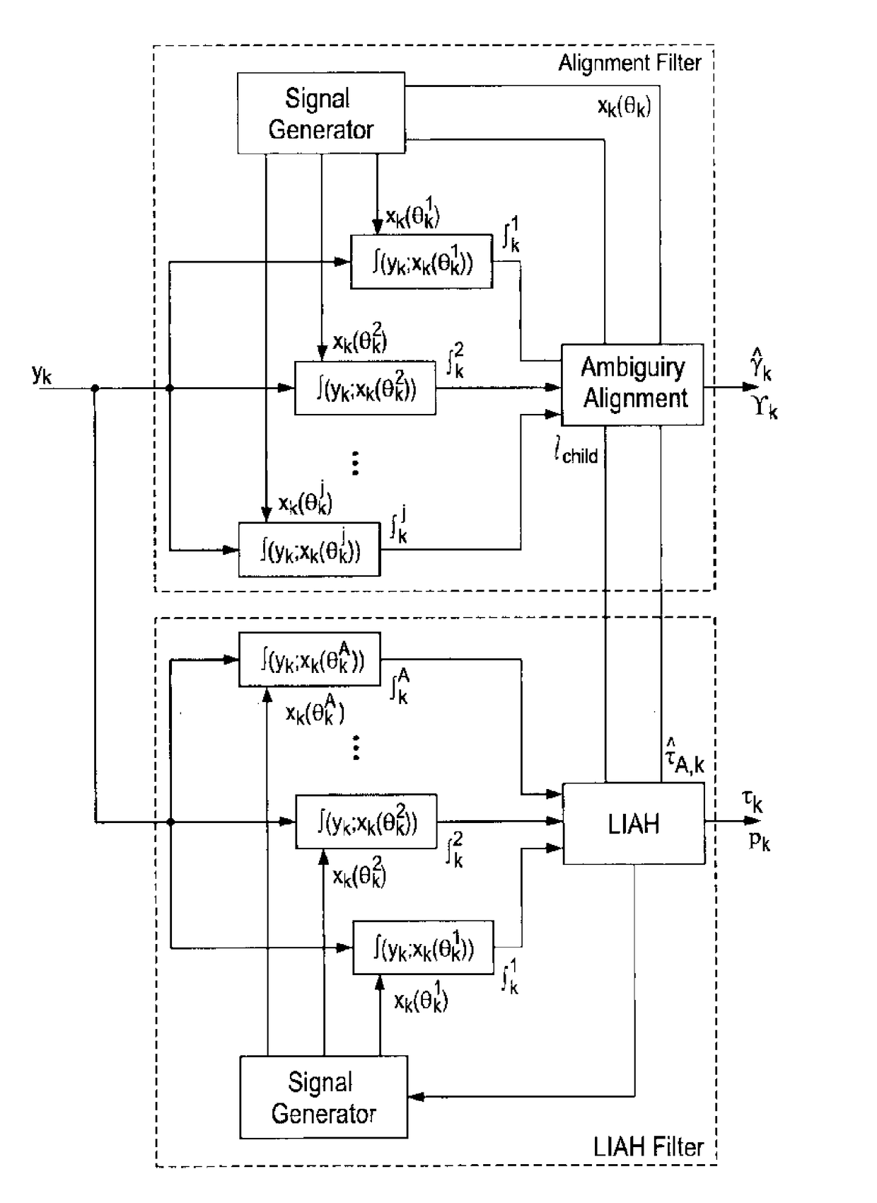
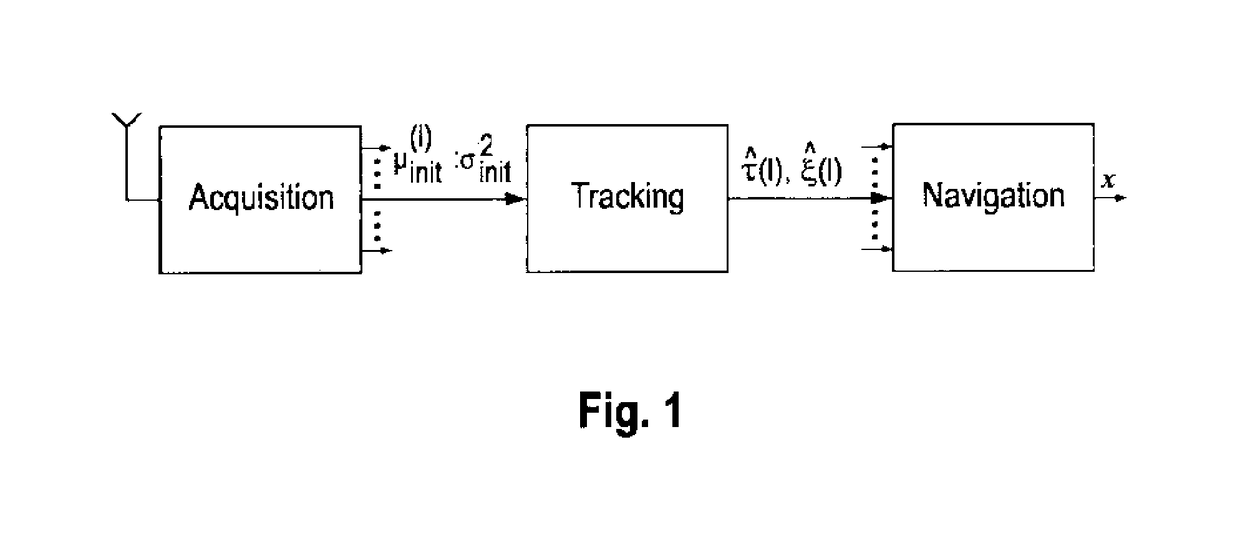
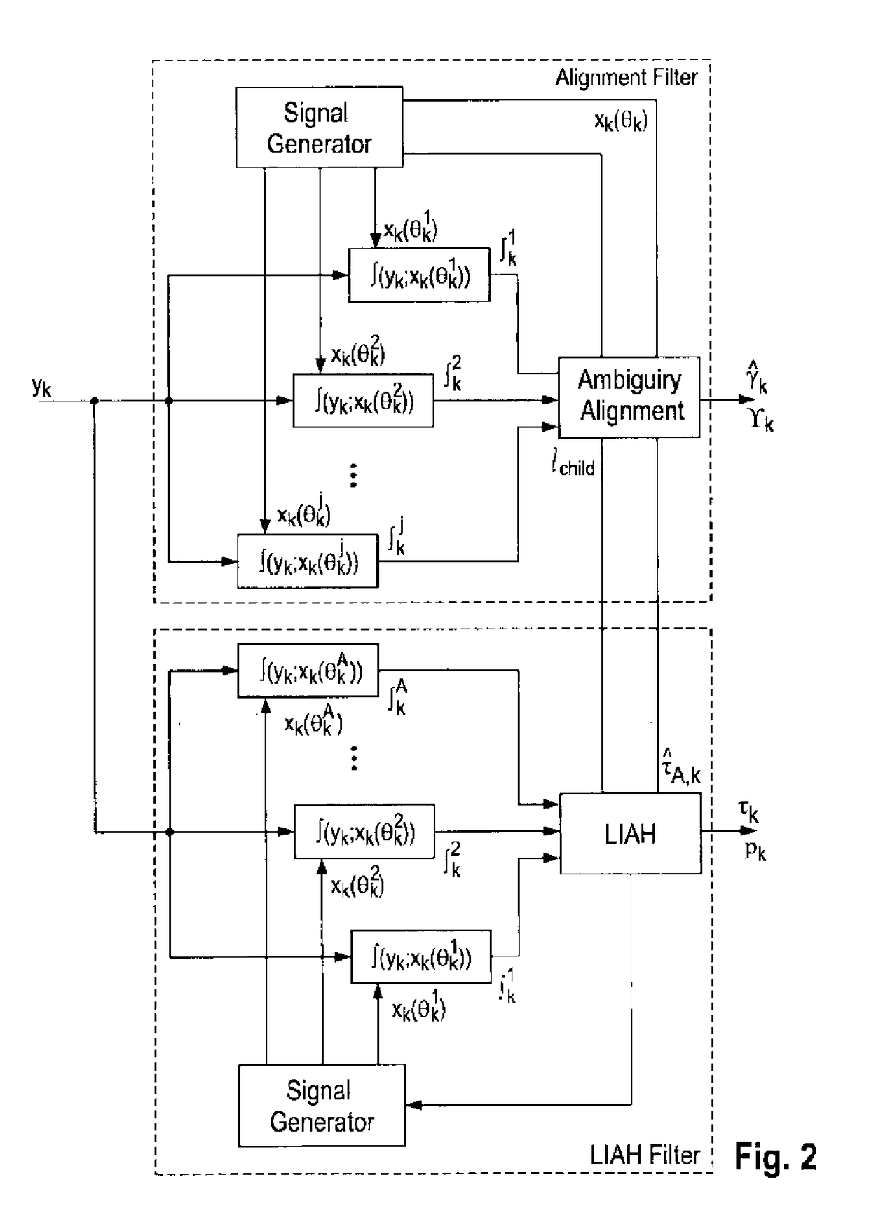
[0102]As will be described in more detail below, the present invention discloses a method wherein it is possible to derive a reliable low-complexity algorithm which enables the full ranging precision provided by the exact measurement (carrier-oriented) model of the line-of-sight propagation delay after a short transient phase to be obtained. According to this exemplary implementation of the present invention, a joint carrier-baseband time-delay estimation is formulated as a state-space estimation problem wherein access to side information about the temporal evolution of the propagation delay process is utilized and signal processing may be performed over subsequent observation blocks. Based on the state-space model, a theoretic Bayesian performance bound and a nonlinear tracking algorithm is formulated which allows to accurately align to the moving set of likelihood extrema. In addition, a LIAH is constructed by evaluating and accumulating the likelihood function in an efficient way...


PUM


Abstract

The present invention relates to a method of determining a distance or location of a remote device or reflector, the method comprising: receiving a signal from a remote signal transmitter associated with or contained in or attached to the remote device; estimating a first propagation delay associated with the received signal, wherein the first propagation delay represents a first candidate for a correct propagation delay; deriving a relationship between the first candidate and one or more other candidates for a correct propagation delay from the received signal; determining a plurality of other candidates for a correct propagation delay based on said relationship; generating a likelihood histogram based on said candidates for a correct propagation delay; selecting a propagation delay from said candidates based on the likelihood histogram; and determining a distance or location of the remote device or reflector using the selected propagation delay.

Description

CROSS-REFERENCE TO RELATED APPLICATIONS[0001]This application is a National Stage Application under 35 U.S.C. § 371 of PCT Application No. PCT / EP2016 / 055380, filed Mar. 11, 2016, which claims priority to German Patent Application No. 102015103605.3, filed Mar. 11, 2015, the entire disclosures of which are hereby incorporated by reference.BACKGROUND OF THE INVENTION[0002]Ranging at high accuracy is a core problem in many technical fields. For example, high precision ranging can increase efficiency and productivity in agriculture by using robots for pruning, weeding and crop-spraying. In marine navigation, ranging with high accuracy can help to enter a port with big ships. Also the landing phase of an airplane can be automated by reliable high precision ranging techniques.[0003]Ranging with radio systems is usually performed by measuring the propagation delay of an electro-magnetic wave with known structure. If the radio signal is transmitted on a high carrier frequency, it is underst...

Claims


Application Information

Patent Timeline
Patent Type & Authority Applications(United States)
IPC IPC(8): G01S11/02G01S5/02G01S13/72G01S19/42
CPCG01S11/02G01S5/0294G01S13/72G01S19/42G01S13/68
Inventor STEIN, MANUELTHEILER, SEBASTIANNOSSEK, JOSEF A.
Owner TECH UNIV MUNCHEN
Why Eureka
Try Eureka