Method and apparatus for recovering in-memory data processing system

Active Publication Date: 2018-08-30
HITACHI LTD
View PDF1 Cites 3 Cited by
  • Summary
  • Abstract
  • Description
  • Claims
  • Application Information

AI Technical Summary

Benefits of technology

The patent text is about methods and devices for a recovery in-memory system that improves memory efficiency and reduces recovery time. The goal is to create a recovery image within shared storage with less recovery time and snapshot writing overhead.

Problems solved by technology

In cases of a failure in the server, the data stored in-memory may be incorrect because of hardware problems, and also external access to the memory of the server externally may become difficult.
Further, in related art implementations involving transaction logs and snapshot images, there may be excessive recovery time in applying the log to the snapshot image.

Method used


Image

  • Method and apparatus for recovering in-memory data processing system
  • Method and apparatus for recovering in-memory data processing system
  • Method and apparatus for recovering in-memory data processing system

Examples


Embodiment Construction

[0025]The following detailed description provides further details of the figures and example implementations of the present application. Reference numerals and descriptions of redundant elements between figures are omitted for clarity. Terms used throughout the description are provided as examples and are not intended to be limiting. For example, the use of the term “automatic” may involve fully automatic or semi-automatic implementations involving user or administrator control over certain aspects of the implementation, depending on the desired implementation of one of ordinary skill in the art practicing implementations of the present application.

[0026]In example implementations as described below, there is the creation of the recovery image within the shared storage.

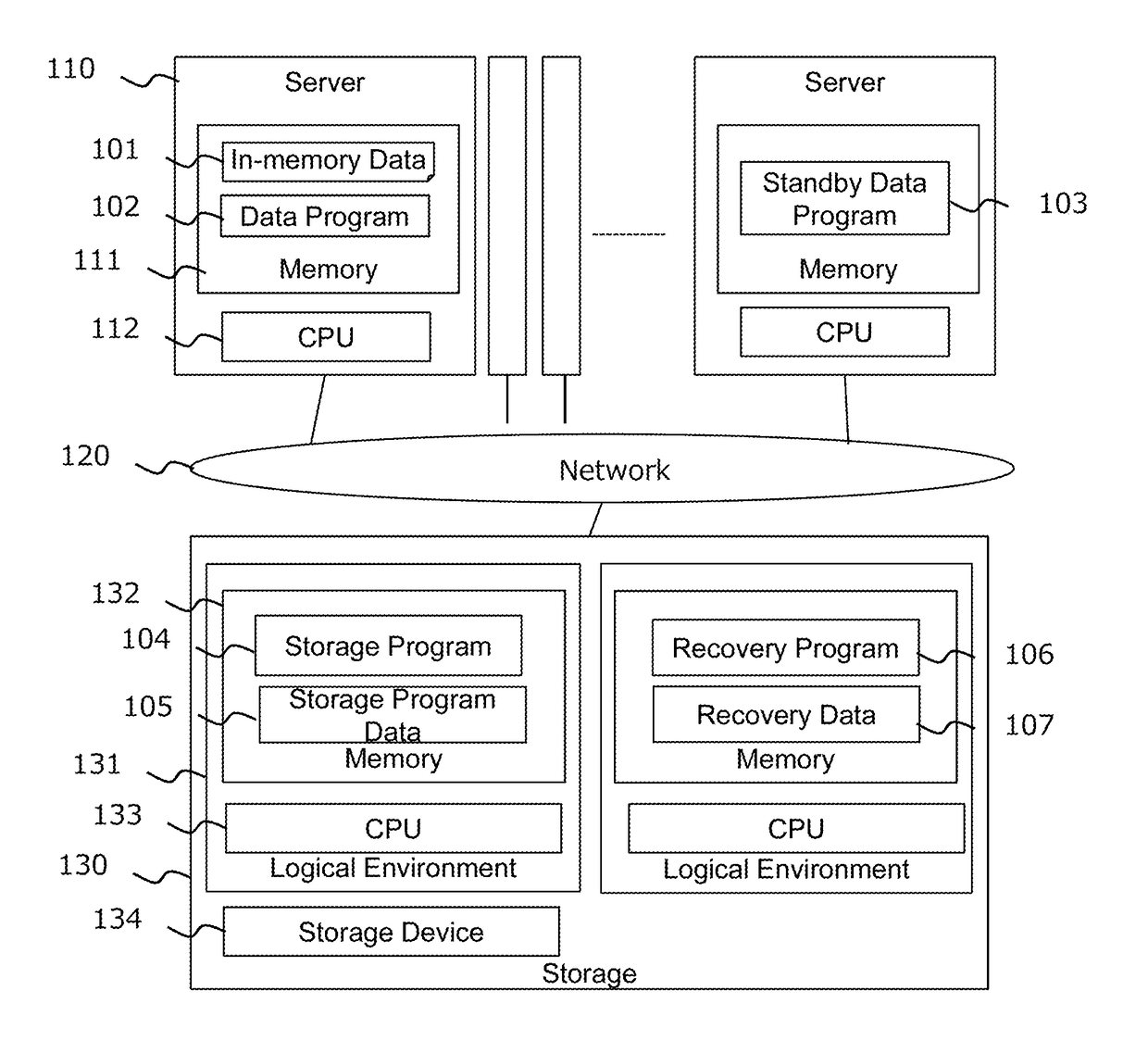
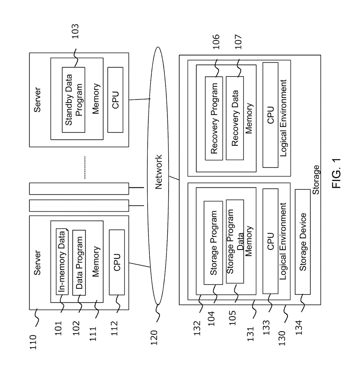
[0027]FIG. 1 illustrates the physical configuration of the system, in accordance with an example implementation. Specifically, FIG. 1 illustrates an example of a physical configuration of the system in which the metho...


PUM


Abstract

Example implementations involve a plurality of servers, network, and storage systems, wherein some of the servers may execute data programs and store primary data in the memory of the servers. Some of the servers may also execute a standby data program. Storage devices may provide for a snapshot volume, a log volume, and a recovery volume, and executes a recovery program to store a recovery image into the recovery volume from the data of the snapshot volume and the log volume. On failure of the server, the standby data program loads the recovery image of the recovery volume, which can reduce the time to commit logs to the snapshot image.

Description

BACKGROUNDField[0001]The present disclosure relates generally to storage systems, and more specifically, to recovery processes for in-memory data processing systems.Related Art[0002]In related art implementations, there are storage architectures involving in-memory computing in the server. In-memory computing utilizes localized resources, such as server random access memory (RAM) to load application to conduct data processing. In-memory computing is utilized in the related art because the memory capacity for each server has become larger, and also includes larger and lower latency non-volatile memory, which allows for processing within the server instead of the storage system.[0003]In cases of a failure in the server, the data stored in-memory may be incorrect because of hardware problems, and also external access to the memory of the server externally may become difficult. In the related art, there are implementations to solve for such failure. In one related art implementation, th...

Claims


Application Information

Patent Timeline
IPC IPC(8): G06F11/14
CPCG06F11/1469G06F11/1451G06F2201/84G06F2201/82G06F16/128
Inventor HATASAKI, KEISUKE
Owner HITACHI LTD
Why Eureka
Try Eureka