Method and apparatus for illuminating an object field imaged by a rectangular image sensor

a rectangular image sensor and object field technology, applied in the field of imaging, can solve the problems of noisy generated image signal and limitation of the amount of heat generated in the enclosed space, and achieve the effects of reducing sensitivity, increasing power level, and reducing sensitivity to some spectral components

Active Publication Date: 2018-09-06
TITAN MEDICAL INC
View PDF0 Cites 6 Cited by
  • Summary
  • Abstract
  • Description
  • Claims
  • Application Information

AI Technical Summary

Benefits of technology

[0023]The image sensor has reduced sensitivity to some spectral components and the desired spectral characteristic may be selected to increase a power level associated with spectral components having reduced sensitivity.
[0024]Projecting the image of the output face of the integrating element may involve projecting the image through a first polarizer such that the object field may be illuminated by polarized light having a first polarization direction and images captured by the image sensor may be captured through a second polarizer having a second polarization direction operable to reduce specular reflections from objects within the object field.

Problems solved by technology

If insufficient light is captured by the imaging system, the generated image signal may be too noisy to produce a useable image representation.
In some applications, such as imaging for laparoscopic surgery, there are limitations on the amount of heat that can be generated within the enclosed space.

Method used


Image

  • Method and apparatus for illuminating an object field imaged by a rectangular image sensor
  • Method and apparatus for illuminating an object field imaged by a rectangular image sensor
  • Method and apparatus for illuminating an object field imaged by a rectangular image sensor

Examples


Embodiment Construction

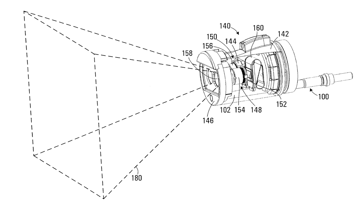
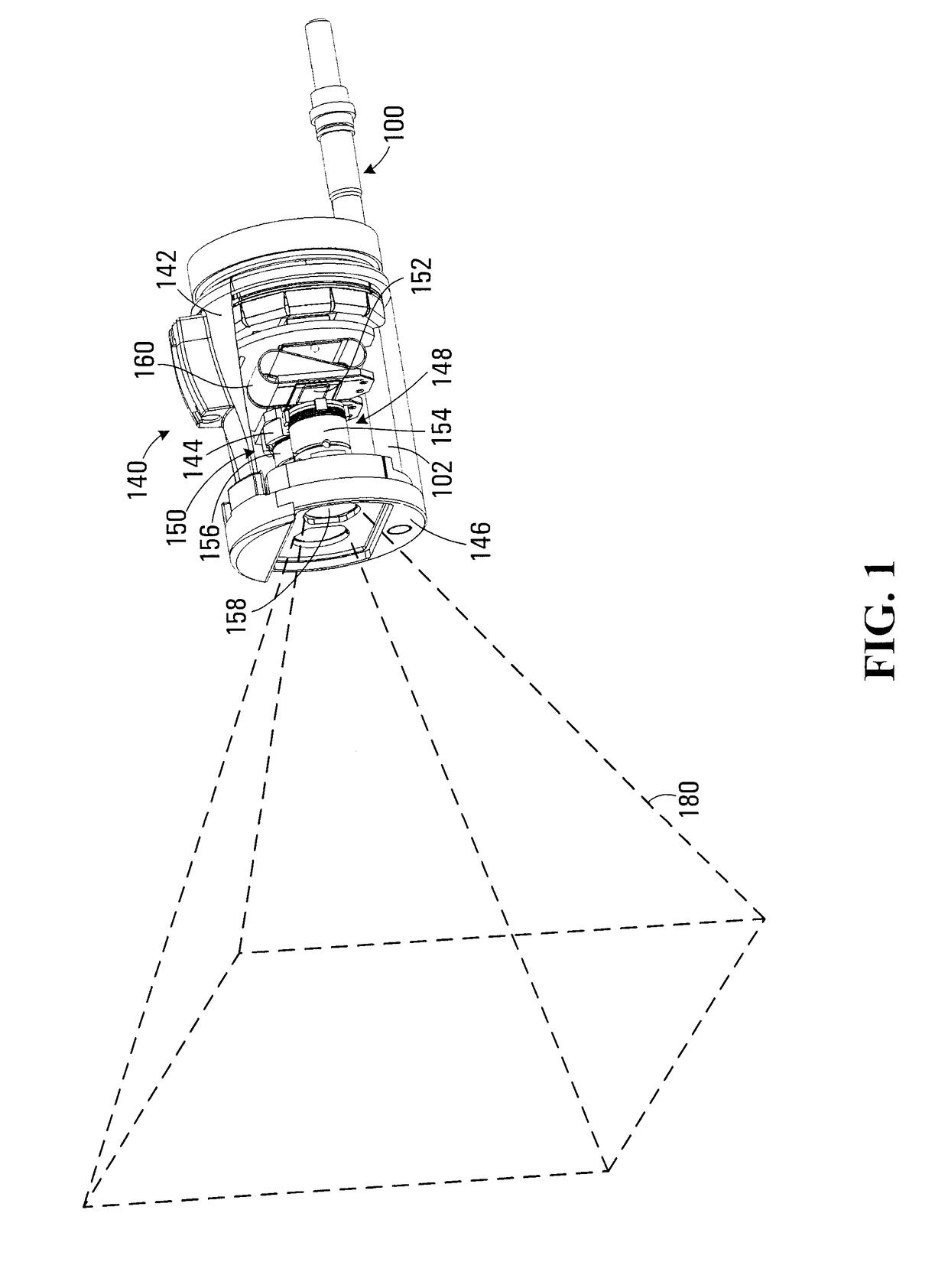
[0032]Referring to FIG. 1, an illuminator apparatus according to a first disclosed embodiment is shown generally at 100. The illuminator apparatus 100 is shown in conjunction with a camera 140. The illuminator apparatus 100 and camera 140 are located within an enclosure 142, which is shown partially cut away in FIG. 1. The illuminator apparatus 100 includes a housing 102 that extends through the enclosure 142 and terminates at a front face 146 of the camera 140.

[0033]In this embodiment the camera 140 includes a first imager 148 and second imager 150, which are spaced apart and configured to generate stereoscopic views of 3 dimensional objects located within an object field 180. The first and second imagers 148 and 150 are symmetrically configured. The first imager 148 includes an image sensor 152 and a lens assembly 154. The second imager 150 also includes an image sensor and a lens assembly 156. In FIG. 1 the image sensor of the second imager 150 is obscured by a mounting bezel 144...


PUM


Abstract

An illuminator apparatus and method for illuminating an object field imaged by a rectangular image sensor having a first aspect ratio is disclosed. The apparatus includes an optical fiber having a proximal end disposed to receive a plurality of input light beams, each light beam having differing spectral properties, the optical fiber being operable to transmit the light beams along the fiber to a distal end of the optical fiber. The apparatus also includes an integrating element disposed to receive the light beams from the distal end of the fiber and combine the light beams to produce a generally homogenous illumination beam at a rectangular output face of the integrating element. The apparatus further includes an illumination projector operable to project an image of the output face of the integrating element into the object field to produce a generally rectangular illuminated region of the object field substantially corresponding to the portion of the object field imaged by the rectangular image sensor.

Description

BACKGROUND1. Field[0001]This disclosure relates generally to imaging and more particularly to illuminating an object field imaged by a rectangular image sensor.2. Description of Related Art[0002]Imaging using CMOS or CCD image sensors relies on the object field being illuminated to enable the imaging system to capture sufficient light for the image sensor to generate an image signal. If insufficient light is captured by the imaging system, the generated image signal may be too noisy to produce a useable image representation. When imaging in enclosed spaces there is usually a lack of ambient light and object field illumination must be provided. In some applications, such as imaging for laparoscopic surgery, there are limitations on the amount of heat that can be generated within the enclosed space. Accordingly there remains a need for improved illumination methods and apparatus for such applications.SUMMARY OF THE INVENTION[0003]In accordance with one disclosed aspect there is provid...

Claims


Application Information

Patent Timeline
Patent Type & Authority Applications(United States)
IPC IPC(8): A61B1/07G03B11/00G03B15/02A61B1/00G03B15/14H04N5/225
CPCA61B1/07G03B11/00G03B15/02A61B1/0017G03B15/14H04N5/2251H04N5/2256A61B1/00096A61B1/00186A61B1/00188A61B1/045A61B1/051A61B1/0638A61B1/0669A61B1/3132A61B1/0655H04N23/56H04N23/50
Inventor CHINNOCK, RANDAL B.WEBER, WILLIAM L.
Owner TITAN MEDICAL INC
Why Eureka
Try Eureka