Clamping Systems and Methods for Robotic Tools

a robotic tool and robotic tool technology, applied in the field of robotic tool clamping systems and methods, can solve the problems of conflicting requirements and achieve the effect of reducing loads

Active Publication Date: 2018-09-06
AEA
View PDF13 Cites 29 Cited by
  • Summary
  • Abstract
  • Description
  • Claims
  • Application Information

AI Technical Summary

Benefits of technology

[0004]The present invention provides, according to a first aspect, an apparatus for clamping a robotically controlled tool to a workpiece, the apparatus comprising: a tool support mountable on a robotic arm and arranged to support the tool; a plurality of clamping modules each of which includes at least one clamping device arranged to clamp the tool support to the workpiece and an adjustment mechanism arranged to allow adjustment of the position of the tool support relative to the workpiece. Clamping of the tool support to the workpiece can reduce the loads that the robot needs to provide or sustain during operation of the tool on the workpiece.

Problems solved by technology

These two requirements are therefore to some extent conflicting.

Method used


Image

  • Clamping Systems and Methods for Robotic Tools
  • Clamping Systems and Methods for Robotic Tools
  • Clamping Systems and Methods for Robotic Tools

Examples


Embodiment Construction

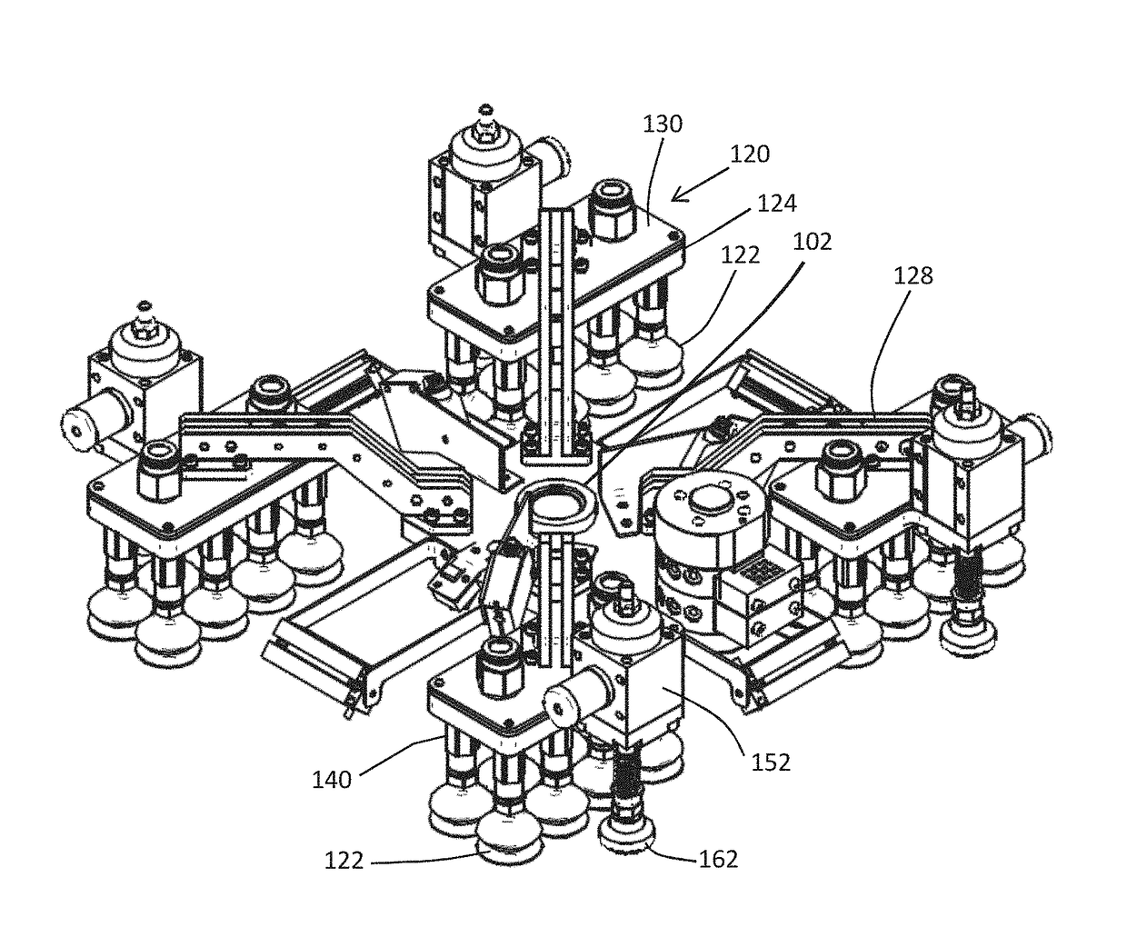
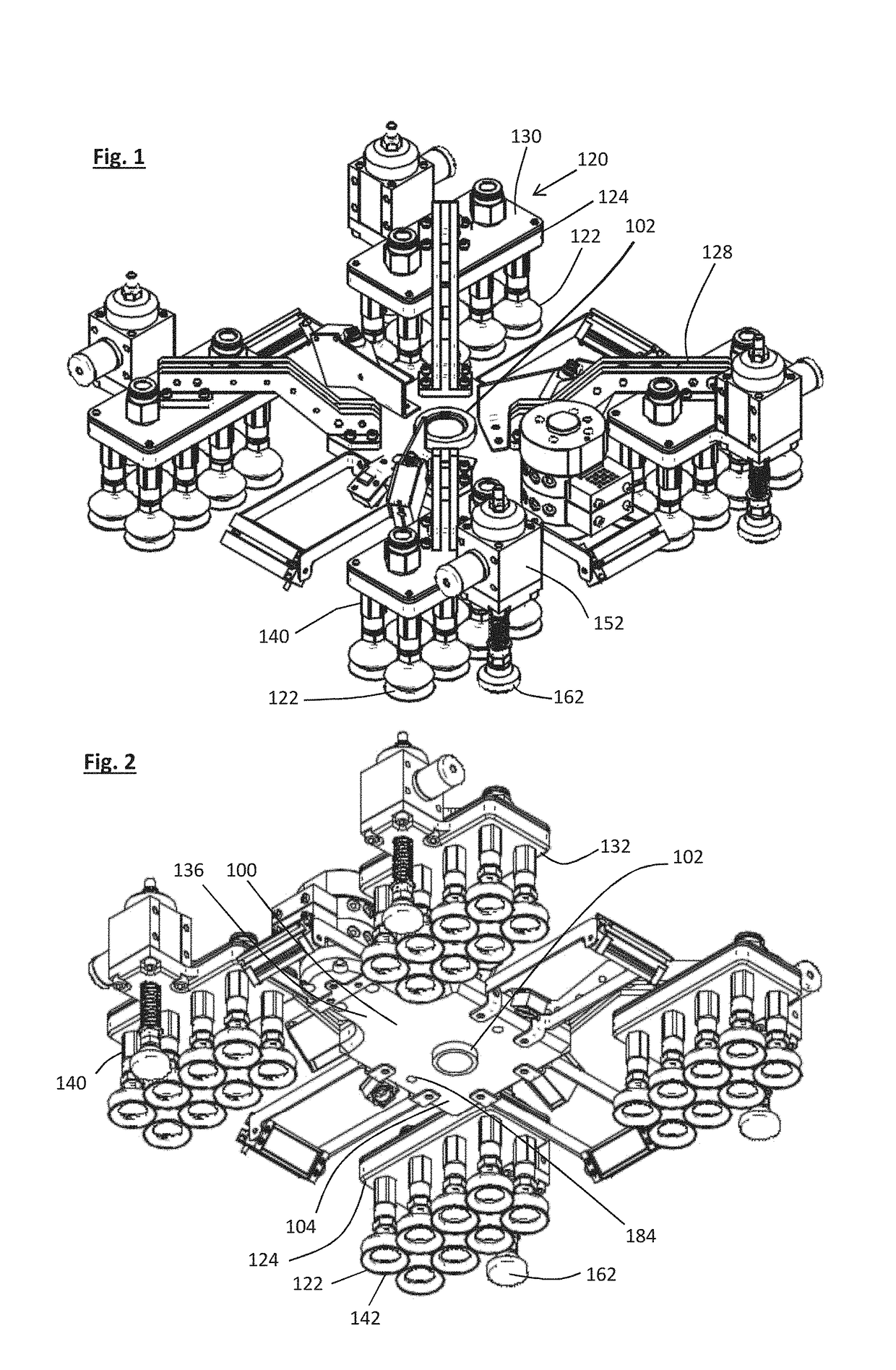
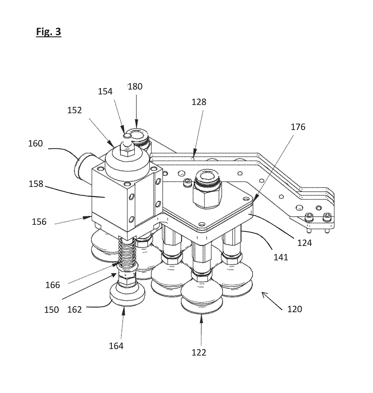
[0035]The clamping system comprises a tool support 100, which may comprise a bush 102 arranged to receive and support a tool such as a drill or riveter. The tool support 100 may further comprise a support plate 104 in which the bush 102 is mounted. The support plate 104 may be substantially rectangular. A plurality of clamping modules 120 may be connected to the tool support 100. The clamping modules 120 may be movable with respect to the tool support 100 (e.g., pneumatically or electrically controlled movement). Each of the clamping modules may each comprise a group of suction cups 122, which may be mounted on a common mounting member, which may conveniently comprise a vacuum housing 124. The vacuum housing 124 may define a vacuum chamber 126. The vacuum chamber 126 may be pneumatically connected to all of the suction cups 122 in the group so that vacuum in the vacuum chamber 126 can be used to activate all of the suction cups 122 in the group. Each of the clamping modules may be c...


PUM

PropertyMeasurementUnit
forceaaaaaaaaaa
vacuumaaaaaaaaaa
flexibleaaaaaaaaaa

Abstract

An apparatus for clamping a robotically controlled tool to a workpiece comprises a tool support mountable on a robotic arm and configured to support the tool, a plurality of clamping modules, each of which includes at least one vacuum cup arranged to clamp the tool support to the workpiece, and an adjustment mechanism configured to adjust the position of the tool support relative to the workpiece.

Description

CROSS-REFERENCES TO RELATED APPLICATIONS[0001]This application claims the benefit of the European patent application No. 17158772.8 filed on Mar. 1, 2017, the entire disclosures of which are incorporated herein by way of reference.FIELD OF THE INVENTION[0002]The present invention relates to clamping systems and methods for robotic tools, and, in particular, to the clamping of robotic tools to workpieces on which the tools operate.BACKGROUND OF THE INVENTION[0003]Robotically operated tools are widely used in a variety of applications, including the manufacture of vehicles such as aircraft. A robot typically includes a robotic arm with an end-effector on which the tool is mounted. For the robotic arm to be easily installed and reconfigured according to variations in the manufacturing process and environment, it is desirable for the arm to be light. However, if the tool is required to apply a force to the workpiece, for example during drilling or riveting, then, if this force is reacte...

Claims


Application Information

Patent Timeline
Patent Type & Authority Applications(United States)
IPC IPC(8): B25J15/06B25J15/00B25H1/00
CPCB25J15/0683B25J15/0061B25H1/0064B23P2700/01B64F5/10B64F5/40B21J15/142B25J11/005B25J15/0095B23Q9/0014B23Q17/2233B23B2215/04B23B2260/118B23B49/026
Inventor BORIA, SÉBASTIENALBERT, FABIENLEPINE, PIERRELATTANZI, LUCACRISTALLI, CRISTINACONCETTONI, ENRICO
Owner AEA
Why Eureka
Try Eureka