Wood chipper with optimized production control

Active Publication Date: 2018-09-06
ASTEC INDS
View PDF4 Cites 4 Cited by
  • Summary
  • Abstract
  • Description
  • Claims
  • Application Information

AI Technical Summary

Benefits of technology

[0008]Among the advantages of a preferred embodiment of the invention is that it provides a drum-type wood chipper that operates at a higher production rate than a machine operating in chipping mode, while maintaining acceptable chip size uniformity. Other advantages and features of this invention will become apparent from an examination of the drawings and the ensuing description.
[0009]The use of the terms “a”, “an”, “the” and similar terms in the context of describing the invention are to be construed to cover both the singular and the plural, unless otherwise indicated herein or clearly contradicted by context. The terms “comprising”, “having”, “including” and “containing” are to be construed as open-ended terms (i.e., meaning “including, but not limited to,”) unless otherwise noted. The terms “substantially”, “generally” and other words of degree are relative modifiers intended to indicate permissible variation from the characteristic so modified. The use of such terms in describing a physical or functional characteristic of the invention is not intended to limit such characteristic to the absolute value which the term modifies, but rather to provide an approximation of the value of such physical or functional characteristic. All methods described herein can be performed in any suitable order unless otherwise specified herein or clearly indicated by context.
[0010]Terms concerning attachments, coupling and the like, such as “connected” and “interconnected”, refer to a relationship wher

Problems solved by technology

However, the presentation of wood to the chipper drum by the feed mechanism causes resistance against the rotation of the chipper drum, and this resistance will slow the rate of rotation of the drum.
However, if the resistance created by the presentation of wood to the chipper drum is large or is generated rapidly, the operator of a conventional wood chipper may not be able to reduce the feed mechanism speed qu

Method used


Image

  • Wood chipper with optimized production control
  • Wood chipper with optimized production control
  • Wood chipper with optimized production control

Examples


Embodiment Construction

[0026]This description of preferred embodiments of the invention is intended to be read in connection with the accompanying drawings, which are to be considered part of the entire written description of this invention. The drawing figures are not necessarily to scale, and certain features of the invention may be shown exaggerated in scale or in somewhat schematic form in the interest of clarity and conciseness.

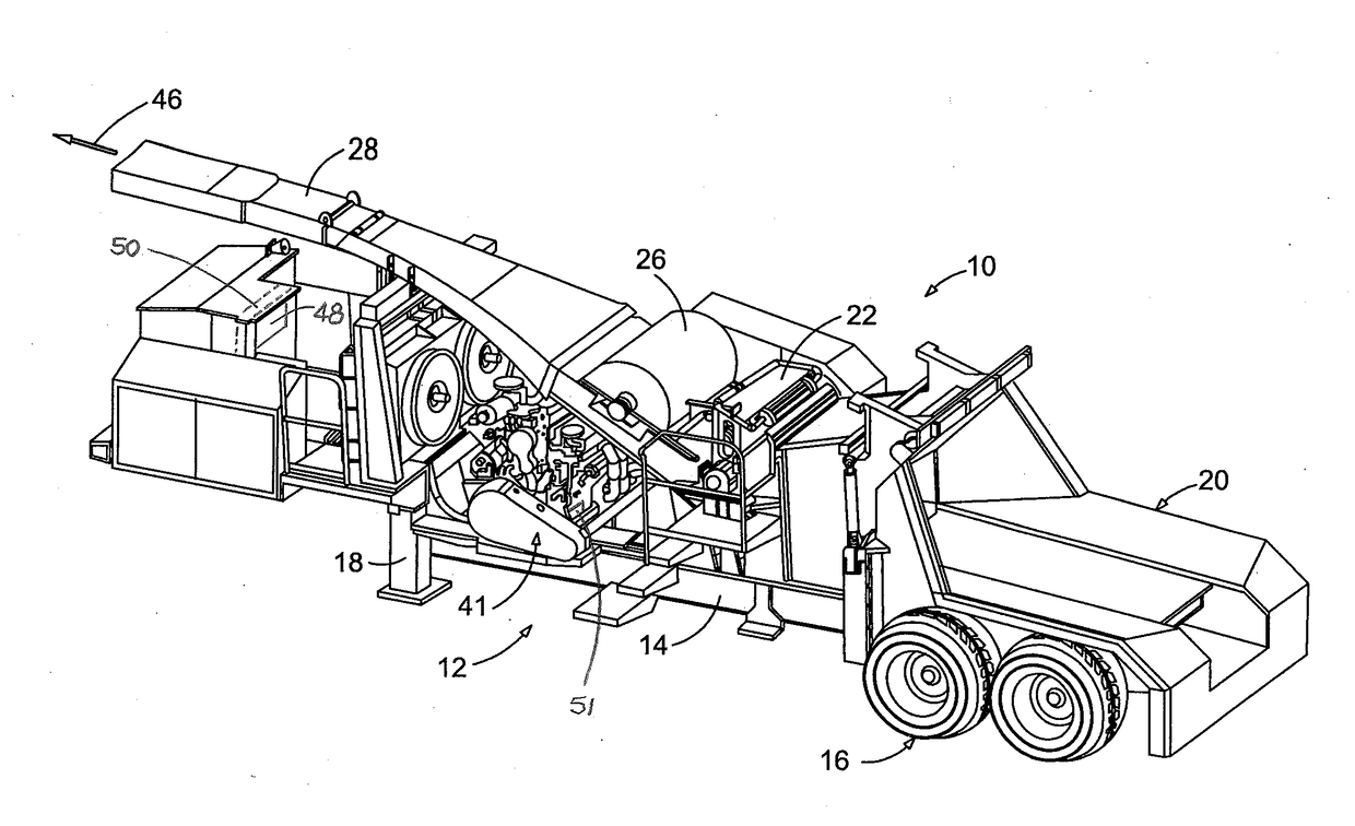
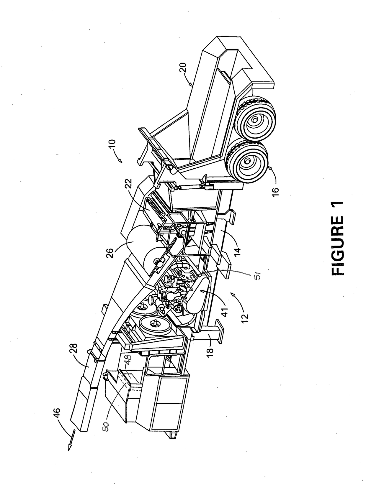
[0027]As shown in FIGS. 1, 2 and 4, a preferred embodiment of the invention comprises a drum-type wood chipper 10 which includes trailer 12 that is adapted to be pulled by a tractor or other vehicle. Trailer 12 includes frame 14 that is supported by wheels 16 and a pair of adjustable support legs, one of which, support leg 18, is shown in FIG. 1. In other embodiments of the invention, the wood chipper can be mounted on a self-propelled frame or chassis, or on a fixed frame. Supported on frame 14 of trailer 12 are feed chute 20 and a chipper drum assembly that is partially encl...


PUM


Abstract

A drum-type wood chipper for processing wood includes a chipper drum that is adapted to rotate about a generally horizontal drum axis, a plurality of cutting blades that are disposed around the periphery of the chipper drum, and an engine that is adapted to rotate the chipper drum about the drum axis. The wood chipper also includes a feed system that is adapted to advance wood to be processed towards the chipper drum, and a controller that is operatively connected to the engine and adapted to determine an instantaneous engine operating rate during rotation of the chipper drum. The controller is also operatively connected to the feed system and adapted to control the rate of advance of wood towards the chipper drum. The controller is also adapted to modify the rate of advance of wood towards the chipper drum as the instantaneous engine operating rate changes while the chipper drum is being rotated.

Description

FIELD OF THE INVENTION[0001]The present invention relates generally to a material reduction machine in the nature of a drum-type wood chipper, and more particularly, to a method and apparatus for optimizing the operating rate of such a machine.BACKGROUND OF THE INVENTION[0002]Material reduction machines in the nature of wood chippers are used to reduce wood to chips of various sizes, depending on their intended use. Generally, such a machine will comprise a reducing assembly having a rotating disk or drum with a plurality of cutting blades mounted around the periphery of the rotating disk or drum. The machine will include an enclosure for the reducing assembly, which enclosure will typically have a feed inlet through which wood materials such as logs and branches to be reduced are introduced, and a discharge outlet through which the chips are discharged after reduction. The use of wood chippers avoids the environmental and other problems associated with burning trees and brush for d...

Claims


Application Information

Patent Timeline
IPC IPC(8): B27L11/02B02C18/22B02C25/00
CPCB27L11/02B02C25/00B02C18/225B02C18/24
Inventor HARNESS, BRADLEY SIMON
Owner ASTEC INDS
Why Eureka
Try Eureka