Vehicle collision prediction algorithm using radar sensor and upa sensor

a technology of collision prediction and radar sensor, applied in the field of collision prediction, can solve the problems of less effective reduction pressure airbags, sensors may not be able to detect a crash, and injuries to drivers, so as to improve the accuracy of airbag deployment and improve the reliability of airbag deploymen

Active Publication Date: 2018-09-06
GM GLOBAL TECH OPERATIONS LLC
View PDF0 Cites 35 Cited by
  • Summary
  • Abstract
  • Description
  • Claims
  • Application Information

AI Technical Summary

Benefits of technology

[0025]Accordingly, it may be possible to address the limitations of physical contact-based airbag deployment algorithms by predicting the crash type, crash point and time of crash to improve airbag deployment reliability with respect to crashes that provide insufficient impulses to the airbag deployment mechanisms. In addition, exemplary embodiments provide a crash prediction algorithm that can improve the accuracy of airbag deployment. Other objects, advantages and novel features of the exemplary embodiments will become more apparent from the following detailed description of exemplary embodiments and the accompanying drawings.

Problems solved by technology

Early airbags would expand rapidly with the driver near the airbag due to the rapid deceleration during a crash and sometimes cause injury to the driver.
However, the reduced pressure airbags were less effective when passengers of a vehicle were not wearing their seat belts.
An issue with airbag deployment and the algorithm that initiates deployment is that sensors may not be able to detect a crash.
Due to the limitations of deployment algorithms, there is a possibility that the airbags will be deployed late or early, or will fail to deploy at all.

Method used


Image

  • Vehicle collision prediction algorithm using radar sensor and upa sensor
  • Vehicle collision prediction algorithm using radar sensor and upa sensor
  • Vehicle collision prediction algorithm using radar sensor and upa sensor

Examples


Embodiment Construction

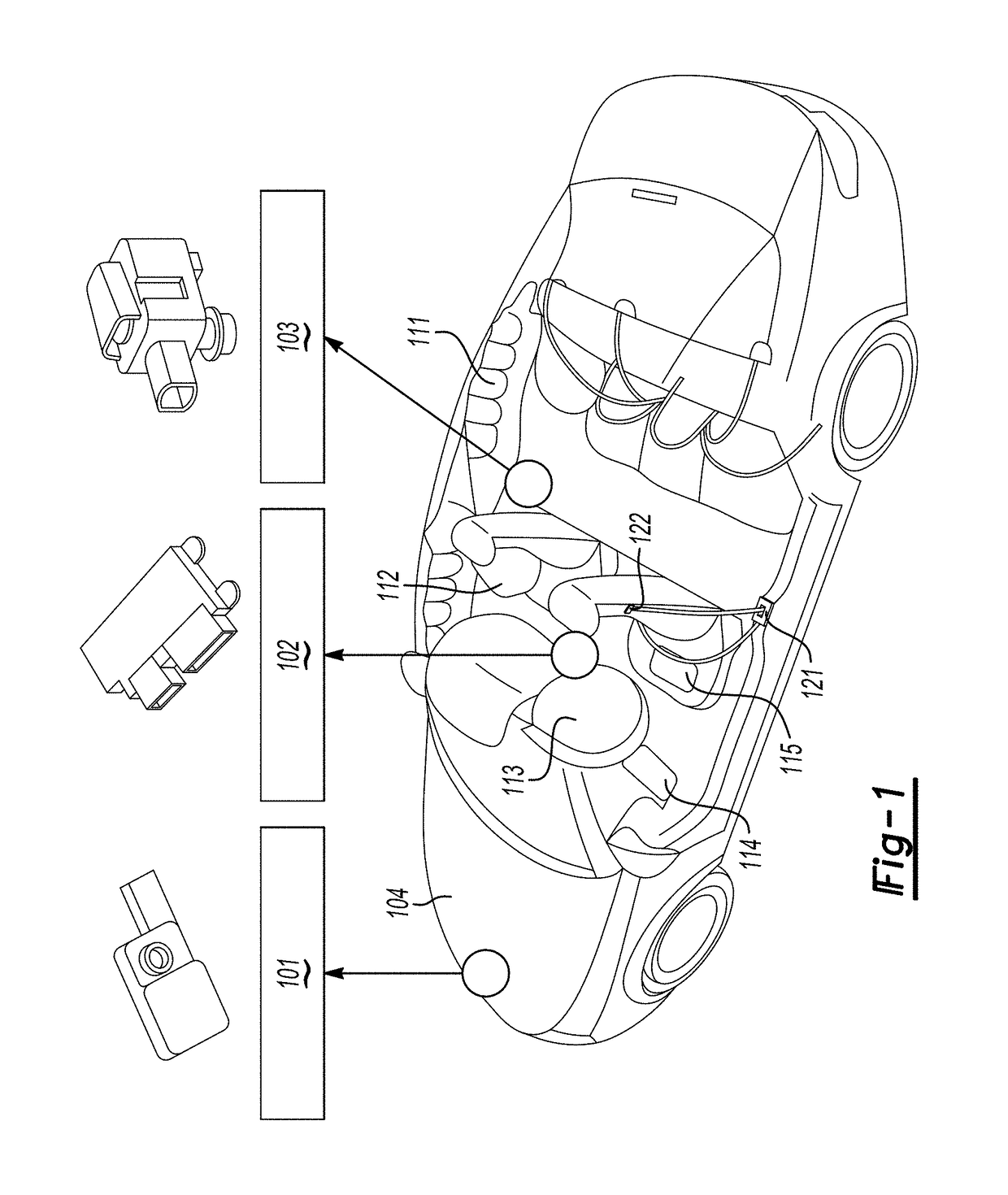
[0040]An apparatus and method that predict a vehicle collision will now be described in detail with reference to FIGS. 1-16 of the accompanying drawings in which like reference numerals refer to like elements throughout the disclosure.

[0041]The following disclosure will enable one skilled in the art to practice the inventive concept. However, the exemplary embodiments disclosed herein are merely exemplary and do not limit the inventive concept to exemplary embodiments described herein. Moreover, descriptions of features or aspects of each exemplary embodiment should typically be considered as available for aspects of other exemplary embodiments.

[0042]It is also understood that where it is stated herein that a first element is “connected to,”“attached to,”“formed on,” or “disposed on” a second element, the first element may be connected directly to, formed directly on or disposed directly on the second element or there may be intervening elements between the first element and the sec...


PUM


Abstract

A method and apparatus of predicting a crash are provided. The method includes detecting coordinates of a target obstacle based on first coordinate information of a radar sensor and second coordinate information of an ultrasonic sensor, translating the second coordinate information to the coordinate system of the first coordinate information and generating translated coordinate information, estimating a position, speed, and acceleration of a vehicle if the vehicle is a predetermined distance from the target obstacle based on the translated coordinate information, determining a potential crash type between the vehicle and the target obstacle based on the estimated position, speed and acceleration of the vehicle, determining a three-dimensional movement trajectory based on the estimated position, speed and acceleration of the vehicle and the determined crash type, and predicting a crash point of the vehicle, a crash point of the target object and a crash time based on the three-dimensional movement trajectory.

Description

CROSS REFERENCE TO RELATED APPLICATIONS[0001]The present application claims priority from Korean Patent Application No. 10-2017-0028375, filed on Mar. 6, 2017 in Korean Intellectual Property Office, the disclosure of which is hereby incorporated by reference herein.INTRODUCTION[0002]Apparatuses and methods consistent with exemplary embodiments relate to crash prediction. More particularly, apparatuses and methods consistent with exemplary embodiments relate to crash prediction algorithms using vehicle sensors and airbag deployment.[0003]Airbag devices in vehicles are an automobile safety technology whose installation is legally mandated in many countries including the United States and Europe. Early airbags would expand rapidly with the driver near the airbag due to the rapid deceleration during a crash and sometimes cause injury to the driver. To address this problem airbags with reduced pressure airbags were developed. However, the reduced pressure airbags were less effective when...

Claims


Application Information

Patent Timeline
Patent Type & Authority Applications(United States)
IPC IPC(8): B60R21/0132B60R21/0134G01S13/93G01S13/86G01S13/60G01S15/93G01S13/931G01S15/931
CPCB60R21/01338B60R21/0134G01S13/931G01S13/862G01S13/60G01S15/931B60R2021/01013B60R2021/01231G01S2013/9364G01S2013/9353G01S2013/9375G01S2015/938B60W30/08B60W30/0953B60W2420/54B60W2420/52B60W2554/00G01S2013/9324G01S2013/932G01S2013/93271B60R19/483G01S2013/93275B60W40/02B60W40/105B60W40/107B60W2520/10B60W2050/0052B60W2552/50B60R2021/0009B60R2021/0004B60R2021/0006B60R2021/0025B60R21/0132B60R2021/0002B60R2021/01286
Inventor LEE, KEUNWOOPARK, KIHONG
Owner GM GLOBAL TECH OPERATIONS LLC
Why Eureka
Try Eureka