Materials management systems and methods

a management system and material technology, applied in the field of material management systems and methods, can solve problems such as misplaced or lost, difficult to track productivity, progress, cost control and safety issues, and pose a risk to surrounding workers and structures

Active Publication Date: 2018-09-06
VERTON IP PTY LTD +2
View PDF6 Cites 7 Cited by
  • Summary
  • Abstract
  • Description
  • Claims
  • Application Information

AI Technical Summary

Benefits of technology

[0013]It is a preferred object of the present invention to provide an improved system and/or method for controlling the orientation of a suspended load and/or ...

Problems solved by technology

In some industries, such as transportation and construction, the diverse nature and geographical spread of the work makes it difficult to track productivity, progress, cost control, and safety issues.
For example, a load may be relocated multiple times before it is put into a final position and therefore may be misplaced or lost.
In some industries, the movement of suspended loads, for example, via cranes, can pose a risk to surrounding workers and structures.
While certain aspects of movement can be controlled by the crane, rotation of a load can often be unpredictable and influenced suddenly by environmental factors, such as wind.
One problem with this approach is that there may be little space for personnel to get well away from the lifted load.
Therefore, while workers are typically not allowed to stand directly under the suspended load for safety reasons, workers will often be required to stand almost under the load but off to one side where there is the possibility of being trapped between the suspended or partially suspended load and a fixed object or structure, or being knocked off a port or deck into the water.
Another problem with this approach is that it can be slow and inaccurate.
One problem with this system is that the moment output of a CMG is limited by the physics of the gyroscope.
In particular, the gyroscope can only provide an output torque through a certain angle of rotation.
This means that the abi...

Method used


Image

  • Materials management systems and methods
  • Materials management systems and methods
  • Materials management systems and methods

Examples


Embodiment Construction

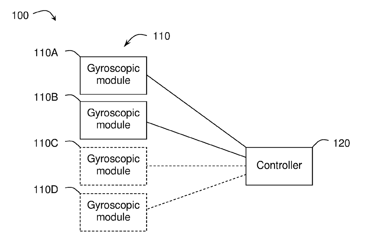
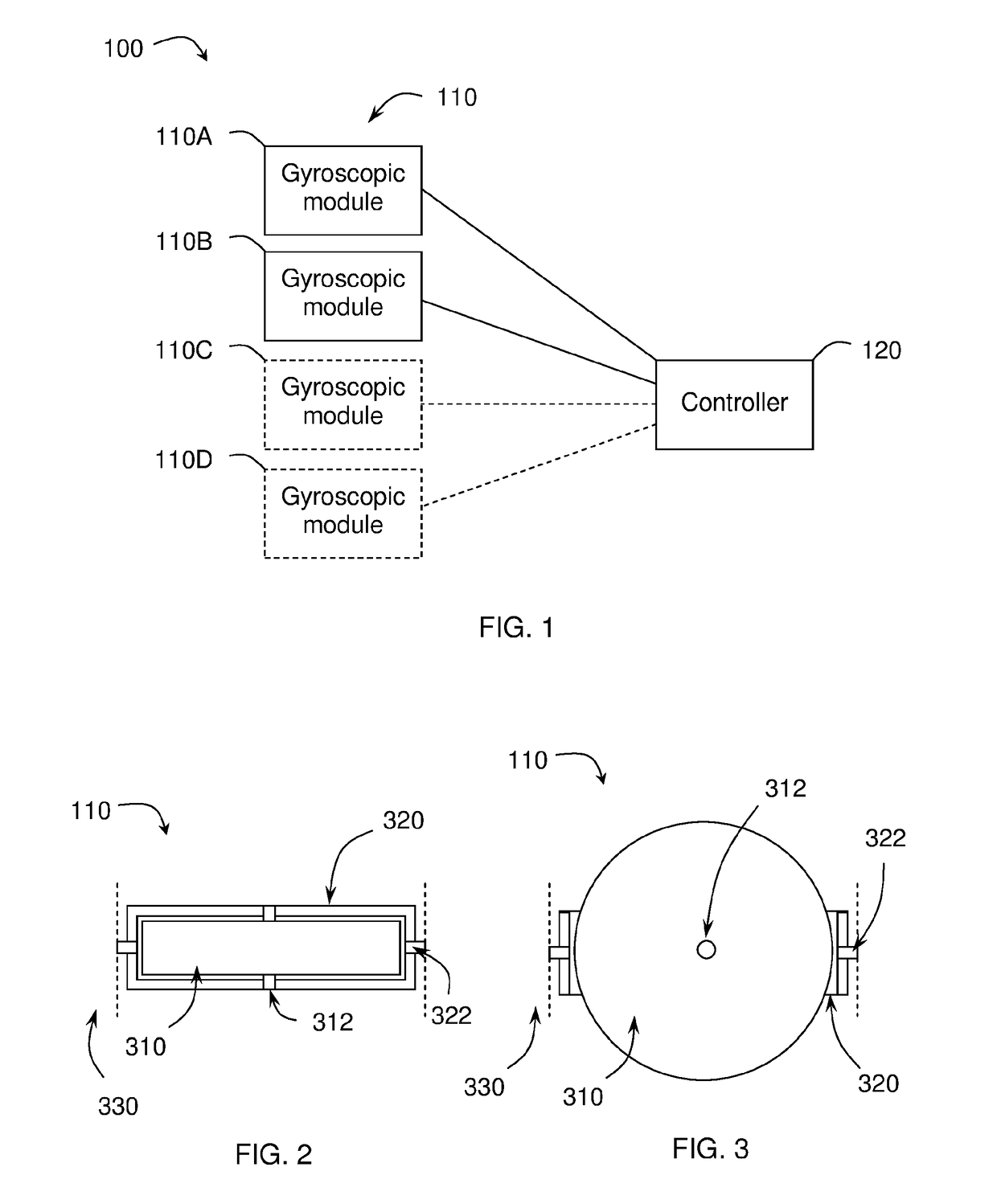
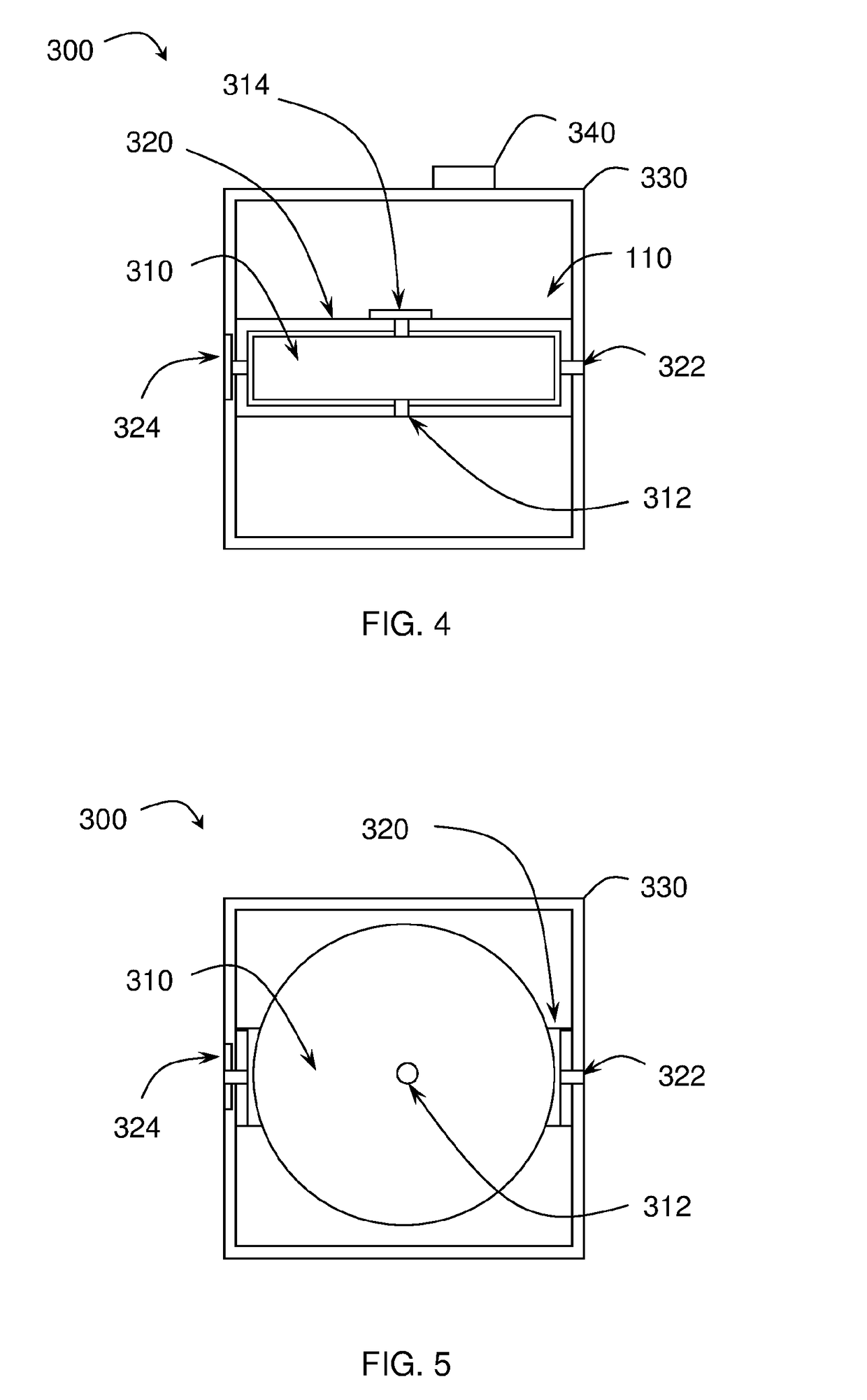
[0131]The present invention relates to materials management systems and methods, and in particular load management systems and methods. In particular, the present invention relates to orienting suspended loads via gyroscopic devices and measuring and generating data about the load and its movements.

[0132]FIG. 1 is a schematic diagram of a system 100 for controlling a rotation of a suspended load according to one embodiment of the invention. The system 100 comprises two or more gyroscopic modules 110 for attachment directly or indirectly to the suspended load. For example, one or more of the gyroscopic modules 110 can be attached directly to the suspended load via an attachment means, such as, a bolt, a clamp or a chain. For example, one or more of the gyroscopic modules 110 can be attached indirectly to the suspended load by attaching them to a load support structure or by attaching them to another gyroscopic module 110 that is attached directly or indirectly to the suspended load. ...


PUM


Abstract

A material management method comprises receiving, via a processor, data relating to work activities and material flows from one or more sensors; generating, via the processor, safety and productivity information based on the data relating to work activities and material flows; comparing, via the processor, the generated safety and productivity information with existing project plans and schedules of the work activities and material flows; determining, via the processor, a present state and relative progress of the project plans and schedules of work; and generating, via the processor, updated project plans and schedules of work. The material can be a load and the method can comprise controlling rotation of a suspended load by attaching two or more gyroscopic modules in communication with the processor directly or indirectly to the suspended load and independently controlling the two or more gyroscopic modules via the processor to control the rotation of the suspended load.

Description

FIELD OF THE INVENTION[0001]The present invention relates to materials management systems and methods including load management systems and methods. In particular, embodiments of the present invention relate to orienting suspended loads via gyroscopic devices and measuring and generating data about loads and their movements, such as on construction sites, ports and in other environments.BACKGROUND TO THE INVENTION[0002]In some industries, such as transportation and construction, the diverse nature and geographical spread of the work makes it difficult to track productivity, progress, cost control, and safety issues. For example, a load may be relocated multiple times before it is put into a final position and therefore may be misplaced or lost.[0003]In some industries, the movement of suspended loads, for example, via cranes, can pose a risk to surrounding workers and structures. While certain aspects of movement can be controlled by the crane, rotation of a load can often be unpred...

Claims


Application Information

Patent Timeline
IPC IPC(8): B66C13/06G06Q10/06
CPCB66C13/06G06Q10/06313G06Q10/06B66C13/08B66C1/10
Inventor THOMSON, STANLEYMILLER, ANDREW
Owner VERTON IP PTY LTD
Why Eureka
Try Eureka