Geared turbofan

a technology of geared turbofans and gas turbine engines, which is applied in the direction of toothed gearings, belts/chains/gearrings, and toothed gearings, can solve the problems of not scaling well to the gear ratio, and achieve the effect of reducing specific fuel consumption and improving propulsive efficiency

Pending Publication Date: 2018-09-06
ROLLS ROYCE PLC
View PDF0 Cites 47 Cited by
  • Summary
  • Abstract
  • Description
  • Claims
  • Application Information

AI Technical Summary

Benefits of technology

[0029]Specific thrust may be in the range 7 to 10 lbf/lbm.s. Specific thrust may be in the range 8 to 9.5 lbf/lbm.s. Specific thrust may be defined as total thrust divided by airflow into the engine. Advantageously these ranges are

Problems solved by technology

One problem with such geared gas turbine engines is that they do not scale

Method used


Image

  • Geared turbofan
  • Geared turbofan

Examples


Embodiment Construction

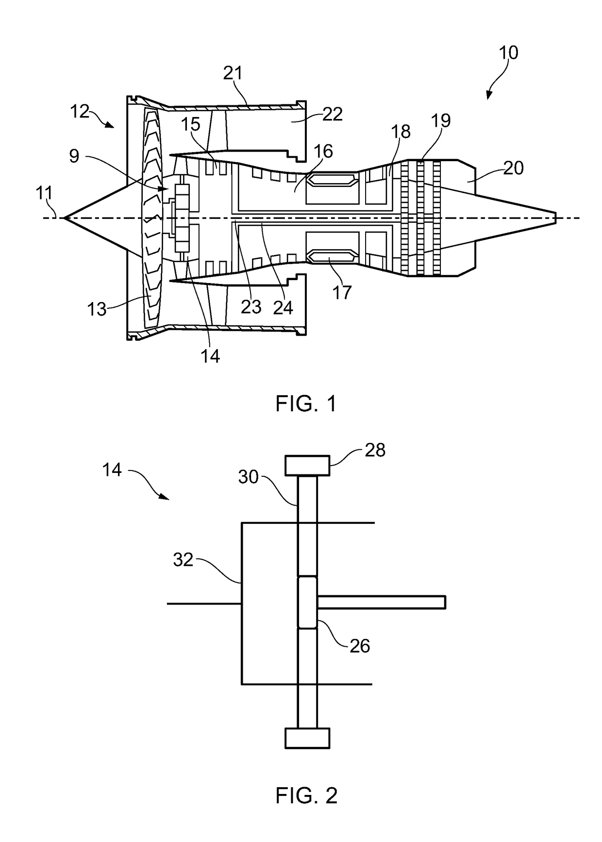
[0034]With reference to FIG. 1, a gas turbine engine is generally indicated at 10, having a principal and rotational axis 11. The engine 10 comprises, in axial flow series, an air intake 12, a propulsive fan 13, a low pressure compressor 15, a high pressure compressor 16, combustion equipment 17, a high pressure turbine 18, a low pressure turbine 19 and a core exhaust nozzle 20. A nacelle 21 generally surrounds the engine 10 and defines the intake 12.

[0035]The gas turbine engine 10 works in the conventional manner so that air entering the intake 12 is accelerated by the fan 13 to produce two air flows: a first air flow into the core 9 of the engine, the low pressure compressor 15, the high pressure compressor 16 and downstream components, as a core flow; and a second air flow which passes through a bypass duct 22 to provide propulsive thrust as a bypass flow. The low pressure compressor 15 compresses the air flow directed into it before delivering that air to the high pressure compr...


PUM


Abstract

A gas turbine engine (10) comprising: a low pressure turbine (19); a fan (13) drivable by the low pressure turbine. A high pressure turbine (18) and a high pressure compressor (16) coupled by a high pressure shaft (24). An epicyclic gearbox (14) in planetary configuration coupled between a low pressure shaft (23) and the fan. The engine having a bypass ratio greater than or equal to 13. Or the fan having a diameter greater than or equal to 85 inches and less than or equal to 170 inches. Or the engine arranged to generate thrust in the range 35,000 lbf to 130,000 lbf.

Description

CROSS-REFERENCE TO RELATED APPLICATION[0001]This application is based upon, and claims the benefit of priority from UK Patent Application No. 1703521.3, filed on 6th Mar. 2017, the entire contents of which are hereby incorporated by reference.BACKGROUNDField of Invention[0002]The present disclosure concerns a geared gas turbine engine with a ducted fan, sometime called a turbofan.Description of Related Art[0003]Gas turbine engines for powering aircraft are well known. In recent years geared gas turbine engines have been developed for small and medium size aircraft. Typically these include an epicyclic gearbox arranged in the star configuration in the low pressure shaft to reduce the speed of the fan relative to the turbine driving it. The star configuration has input drive via the rotating sun gear, output via the rotating ring gear and a set of planet gears which rotate about fixed axes.[0004]One problem with such geared gas turbine engines is that they do not scale well to the gea...

Claims


Application Information

Patent Timeline
IPC IPC(8): F02C7/36F16H1/28F02K3/06
CPCF02C7/36F16H1/28F02K3/06F05D2260/40311F05D2220/323F05D2220/36
Inventor POINTON, JAMES M.BRADBROOK, STEPHEN J.
Owner ROLLS ROYCE PLC
Why Eureka
Try Eureka