Electrostatic chuck device

a technology of electrostatic chuck and chuck body, which is applied in the direction of electrostatic holding device, metal-working machine components, manufacturing tools, etc., can solve the problems of affecting the performance of the electrostatic chuck device, and achieve the effect of prolonging the li

Active Publication Date: 2018-09-06
SUMITOMO OSAKA CEMENT CO LTD
View PDF0 Cites 193 Cited by
  • Summary
  • Abstract
  • Description
  • Claims
  • Application Information

AI Technical Summary

Benefits of technology

[0022]According to the present invention, an electrostatic chuck device in which it is possible to prolong the life can be provided.

Problems solved by technology

In such an electrostatic chuck device, the adhesive is etched by plasma or the like which is used in a semiconductor manufacturing process, and thus there is a case where the performance of the electrostatic chuck device is affected.

Method used


Image

  • Electrostatic chuck device
  • Electrostatic chuck device
  • Electrostatic chuck device

Examples


first embodiment

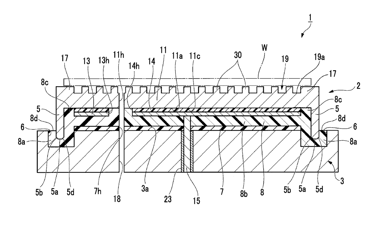
[0029]Hereinafter, an electrostatic chuck device 1 according to a first embodiment which is a preferred example of the present invention will be described with reference to FIG. 1. In the drawings which are used in the following description, in order to make the features easy to understand, there is a case where characteristic portions are shown in an enlarged manner for convenience. Therefore, dimensions, ratios, or the like of the respective constituent elements is not necessarily the same as the actual.

[0030]FIG. 1 is a sectional view of the electrostatic chuck device 1. The electrostatic chuck device 1 of this embodiment has a circular shape when viewed in a planar view. The electrostatic chuck device 1 is provided with an electrostatic chuck member 2 having an upper surface which is amounting surface 19 on which a plate-shaped sample W such as a semiconductor wafer is mounted, a temperature controlling base member 3 for controlling the temperature of the electrostatic chuck mem...

modification example 1

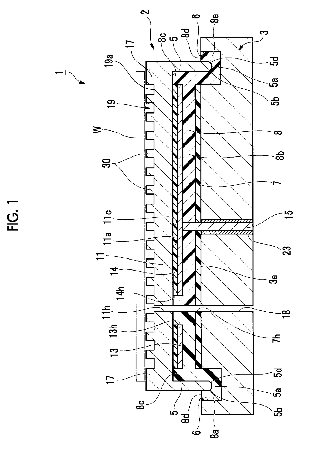
[0092]Next, an electrostatic chuck device 101 of Modification Example 1 which is a preferred example of the present invention will be described.

[0093]FIG. 2 is a partial sectional view of the electrostatic chuck device 101. The electrostatic chuck device 101 of Modification Example 1 is different from the electrostatic chuck device 1 of the above-described embodiment mainly in terms of the configurations of the dike portion and the groove portion. The constituent elements of the same aspect as that of the above-described embodiment are denoted by the same reference numerals and description thereof is often omitted.

[0094]The electrostatic chuck device 101 is provided with an electrostatic chuck member 102, a temperature controlling base member 103, an adhesive layer 108, and the second organic insulating layer 7. The electrostatic chuck member 102 has a mounting plate (a ceramic plate) 111 on which the plate-shaped sample W is mounted, the electrode for electrostatic attraction 13, a...

modification example 2

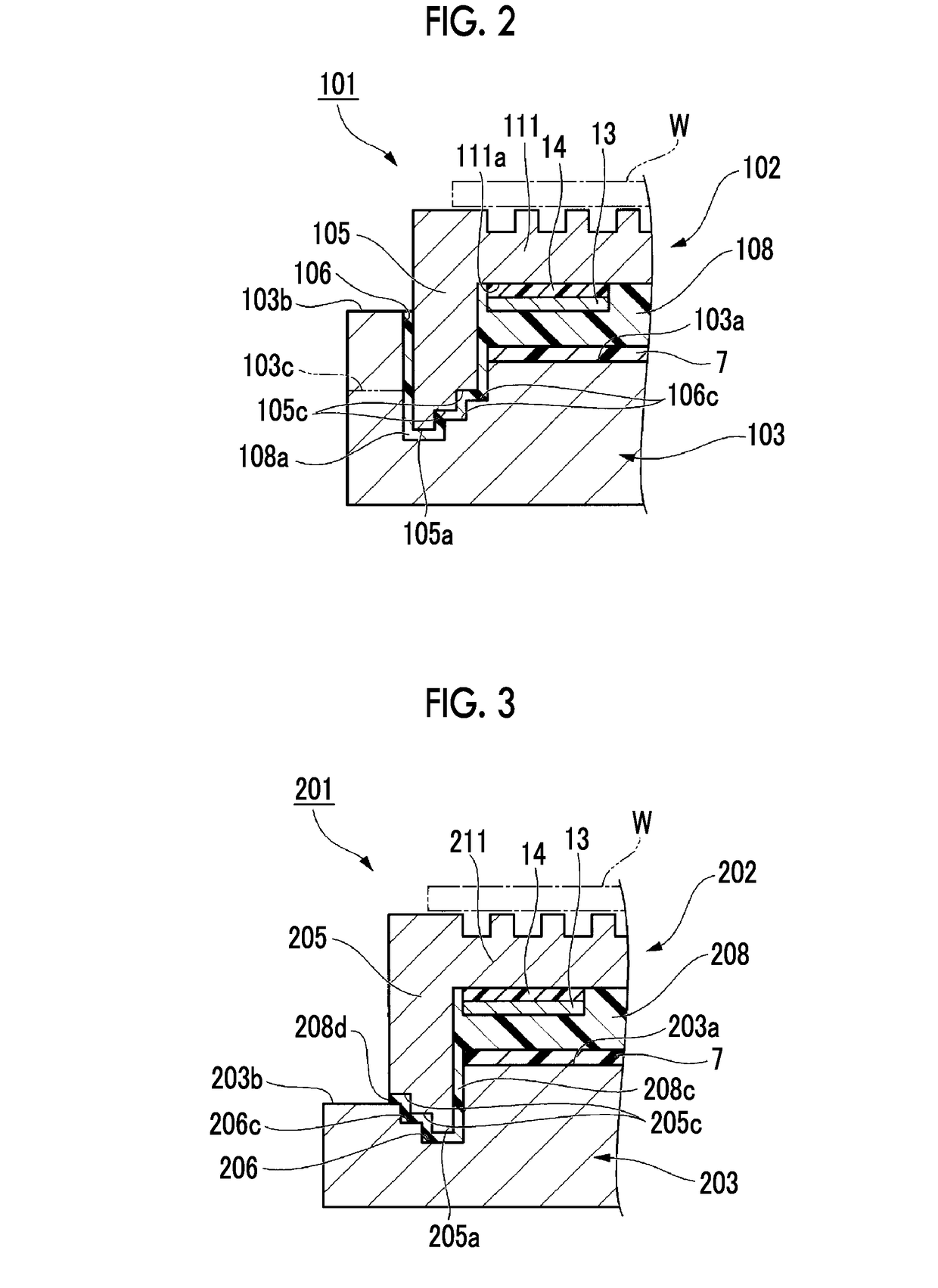
[0099]Next, an electrostatic chuck device 201 of Modification Example 2 which is a preferred example of the present invention will be described.

[0100]FIG. 3 is a partial sectional view of the electrostatic chuck device 201. The electrostatic chuck device 201 of Modification Example 2 has a combination of a dike-portion-side step surface and a groove-portion-side step surface, similar to the electrostatic chuck device 101 of Modification Example 1, and specifically has a dike-portion-side step surface 205c and a groove-portion-side step surface 206c. However, a position and a direction in which the dike-portion-side step surface 205c and the groove-portion-side step surface 206c are provided are different from those in Modification Example 1. The constituent elements of the same aspect as those of the above-described embodiment and modification example are denoted by the same reference numerals and description thereof is often omitted.

[0101]The electrostatic chuck device 201 is provi...


PUM


Abstract

An electrostatic chuck device includes an electrostatic chuck member and a temperature controlling base member. The electrostatic chuck member has a ceramic plate having a mounting surface on which a plate-shaped sample is mounted, and an electrode for electrostatic attraction provided on the other surface on the side opposite the mounting surface of the ceramic plate. The temperature controlling base member is disposed on the surface on the side opposite the ceramic plate side of the electrode for electrostatic attraction and cools the electrostatic chuck member. The ceramic plate has a dike portion which extends to the temperature controlling base member side and surrounds the electrode for electrostatic attraction, the temperature controlling base member has a groove portion accommodating an end part of the dike portion, and a space between the groove portion and the dike portion is filled with a filling part formed of a resin material.

Description

TECHNICAL FIELD[0001]The present invention relates to an electrostatic chuck device.[0002]This application claims the right of priority based on Japanese Patent Application No. 2015-168230 filed on Aug. 27, 2015, the entire content of which is incorporated herein by reference.BACKGROUND ART[0003]In a semiconductor manufacturing apparatus, in the past, as a device for simply mounting and fixing a plate-shaped sample such as a wafer or a glass substrate to a sample stage, an electrostatic chuck device using an electrostatic attraction mechanism has been used. As the configuration of the electrostatic chuck device of the related art, there is known a configuration having an attraction plate having a structure in which an electrode is buried in a dielectric body, and a support body for supporting the attraction plate through an adhesive. In such an electrostatic chuck device, the adhesive is etched by plasma or the like which is used in a semiconductor manufacturing process, and thus th...

Claims


Application Information

Patent Timeline
Patent Type & Authority Applications(United States)
IPC IPC(8): H01L21/683H01L21/3065H02N13/00B23Q3/15H01L21/67
CPCH01L21/6833H01L21/3065H02N13/00B23Q3/15H01L21/6835H01L21/67109H01L21/67248H01L21/6831H01L21/6875H01L21/683
Inventor KOSAKAI, MAMORUMAETA, SHINICHIMAEDA, KEISUKE
Owner SUMITOMO OSAKA CEMENT CO LTD
Why Eureka
Try Eureka