Facilitated stretching machine

Active Publication Date: 2018-09-13
BLACKMORE ROBERT F
View PDF4 Cites 3 Cited by
  • Summary
  • Abstract
  • Description
  • Claims
  • Application Information

AI Technical Summary

Benefits of technology

[0009]In one embodiment, the present invention is a system to facilitate stretching for a user, including a force-applying component and a subject-engaging surface, such that the force applying element is attached to a first end of a rotatable element that rotates about a first

Problems solved by technology

Individuals who exercise alone often find themselves using stationary implements, or a wall, to stretch against, but methods still do not provide the same level of stretching that a trainer could provide.
Attempting stretches alone is especially troublesome for the elderly or those with physical disabilities, because they ofte

Method used


Image

  • Facilitated stretching machine
  • Facilitated stretching machine
  • Facilitated stretching machine

Examples


first embodiment

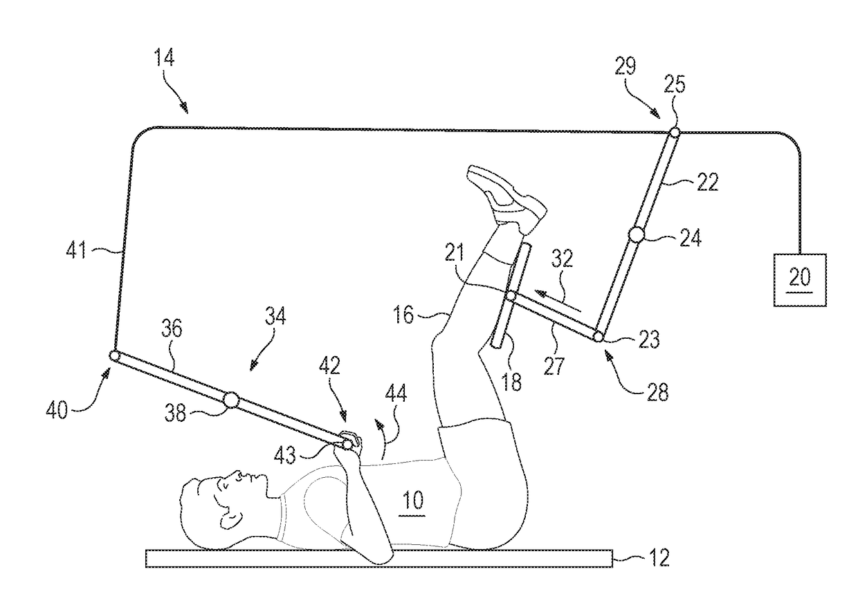
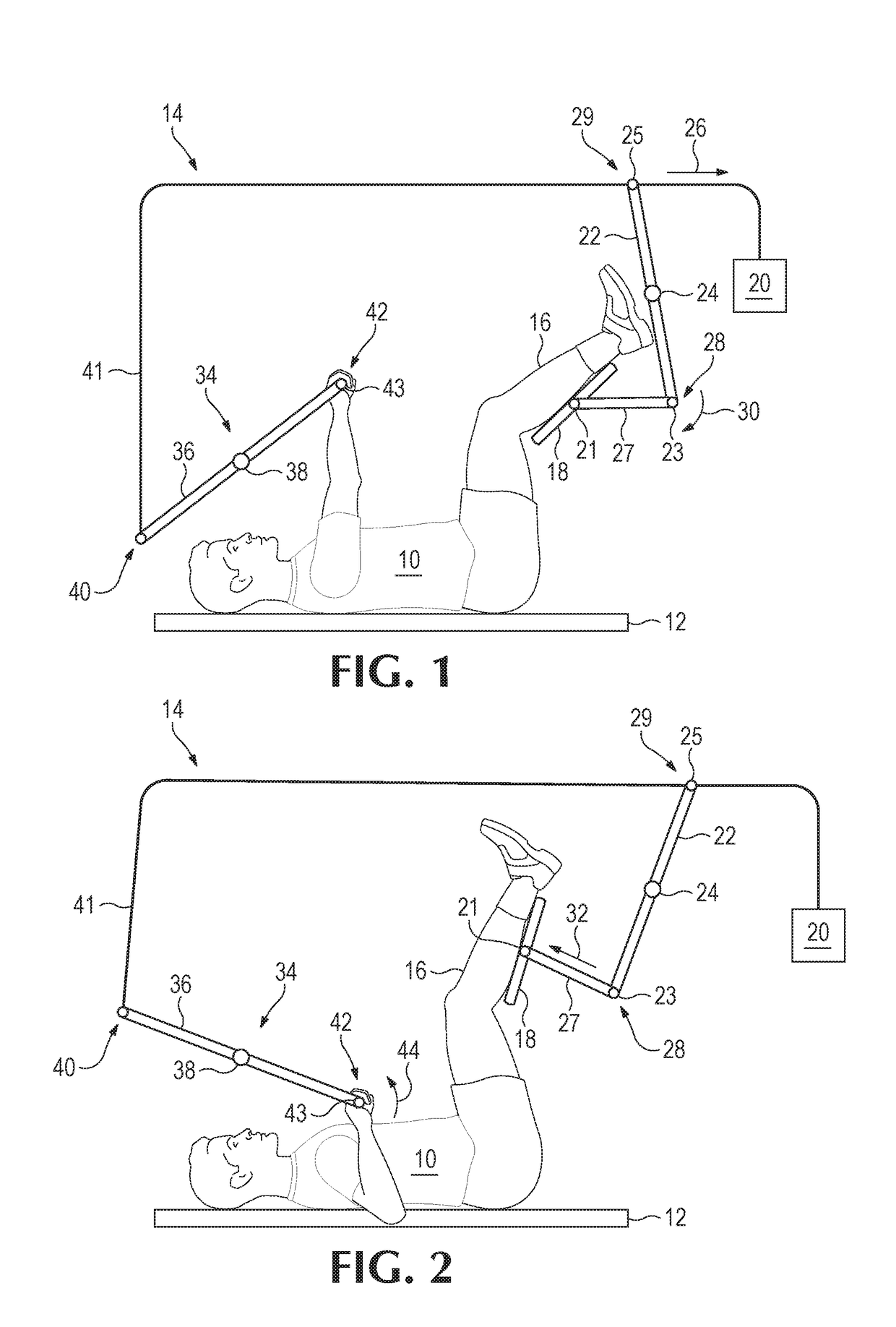
[0019]FIG. 1 shows a user or subject 10 laying on his back on a supporting surface 12. In such a first embodiment, the user 10 interacts with the system 14 by placing one or both legs 16 on a first element, or a subject-engaging surface 18. The surface 18 may be rectangular or be specifically shaped to fit a user's leg or the both of the user's legs. The surface 18 may be operatively connected to a second element, or a force-applying element 20 by a rotatable bar or device 22 that rotates about a first point of secured support, or fulcrum 24, and three pivoting hinges 21, 23, and 25. When the force-applying element 20, is applied, the first end 29 of the rotatable bar 22 moves in the direction of the force, such that the hinge 25 supports rotation in a clockwise direction, represented by the arrow 26 in FIG. 1, about the first fulcrum 24. The second end 28 of the rotatable bar 22 moves in a first rotational direction, the direction represented by arrow 30 in FIG. 1, aided by hinge 2...

second embodiment

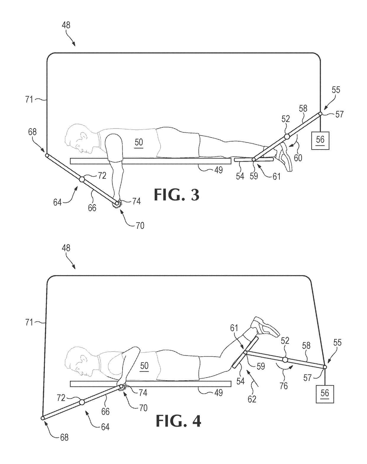
[0022]FIGS. 3 and 4 represent the stretching device 48 that may function to stretch a user's 50 hip flexors and / or abdominal muscles and / or other surrounding muscles. In use, the user 50 first lays on his or her stomach on a surface 49. The stretching device 48 may have a first point of secured support, or fulcrum 52 that is operatively connected to subject-engaging surface 54. Similar to the device 14, a force-applying element 56 may be used to selectively apply force to a user's target body part(s) with the use of rotatable bar or device 58, and hinges 57 and 59. In this embodiment of the present invention, application of a force causes the first end 55 of the rotatable bar 58 to rotate about the first fulcrum 52 in a first rotational direction, or a clockwise manner, as represented by arrow 60, pivoting about both hinges 57 and 59, and causing the second end 61 of the rotatable bar 58 to apply pressure to the user 50 via the subject engaging surface 54. Such rotation causes the s...

third embodiment

[0024]the present in FIGS. 5 and 6 shows a user 78 using a third stretching device 80 for stretching the user's 78 upper body. In such an embodiment, the user 78 may be positioned in a seat 82 having a back support 84 that may function to resist pressure applied by the subject engaging surface 86. The subject-engaging surface 86 is operatively connected to a first point of secured support, or fulcrum 88 via a rotatable bar or device 90, hinges 91 and 92, and elongate element 95. As viewable in FIGS. 5 and 6, one end 83 of the rotatable bar 90 is operatively connected to the subject engaging surface 86 via a hinge 92. The opposing end 85 of the rotatable bar 90 is connected to a force-applying element 94 via a hinge 93, such that when force is applied by the force-applying element 94, the bar 90 rotates in a first rotational direction, or a clockwise direction, as represented by arrow 96. Therefore, when force is selectively applied via the force-applying element 94, the bar 90 rotat...


PUM


Abstract

A system to facilitate stretching for a user, including a force-applying component and a subject-engaging surface, such that the force applying element is attached to a first end of a rotatable element that rotates about a first point of secured support, or fulcrum, and the subject engaging surface is operatively connected to a second end of said rotatable element, such that application of force via the force-applying component causes rotational movement of the subject-engaging surface toward the user.

Description

CROSS REFERENCE TO RELATED APPLICATIONS[0001]Not Applicable.STATEMENT REGARDING FEDERALLY SPONSORED RESEARCH OR DEVELOPMENT[0002]Not Applicable.THE NAMES OF THE PARTES TO A JOINT RESEARCH AGREEMENT[0003]Not Applicable.INCORPORATION-BY-REFERENCE OF MATERIAL SUBMITTED ON A COMPACT DISC OR AS A TEXT FILE VIA THE OFFICE ELECTRONIC FILING SYSTEM (EFS WEB)[0004]Not Applicable.STATEMENT REGARDING PRIOR DISCLOSURES BY THE INVENTOR OR A JOINT INVENTOR[0005]Not Applicable.BACKGROUND OF THE INVENTION[0006]The subject matter of this application relates to exercise equipment that facilitates stretching exercises without the need for help of a personal trainer.[0007]The importance of fitness and exercise is becoming increasingly prevalent within the daily lives of many people beyond those of athletes. Stretching is frequently included within many exercise regimens due to many inherent physical and mental benefits that come with stretching. Some benefits of engaging in a proper stretching regimen ...

Claims


Application Information

Patent Timeline
IPC IPC(8): A63B23/00A63B21/06A63B21/00
CPCA63B23/00A63B21/0615A63B2023/006A63B21/4039A63B21/151A61H1/0237A61H1/0274A61H1/0292A61H2201/1276A61H2201/1635A61H2201/164A61H2201/1671A61H2201/1676A61H2203/0425A61H2203/0456A61H2203/0468A63B21/00185A63B21/0552A63B23/03525A63B23/03583A63B2208/0233A63B2208/0238A63B2208/0247A63B2208/0257A63B2225/102A63B21/0628A63B21/4029A63B21/4034A63B21/4035
Inventor BLACKMORE, ROBERT F.
Owner BLACKMORE ROBERT F
Why Eureka
Try Eureka