
Systems and methods for interleaving multiple active camera frames

a camera frame and active technology, applied in the field of systems and methods for interleaving multiple active camera frames, can solve problems such as cross-contamination between sensors, incorrect depth calculations, and unwanted signal/noise in the ir imag

Active Publication Date: 2018-09-13
MICROSOFT TECH LICENSING LLC
View PDF6 Cites 6 Cited by
  • Summary
  • Abstract
  • Description
  • Claims
  • Application Information

AI Technical Summary

Benefits of technology

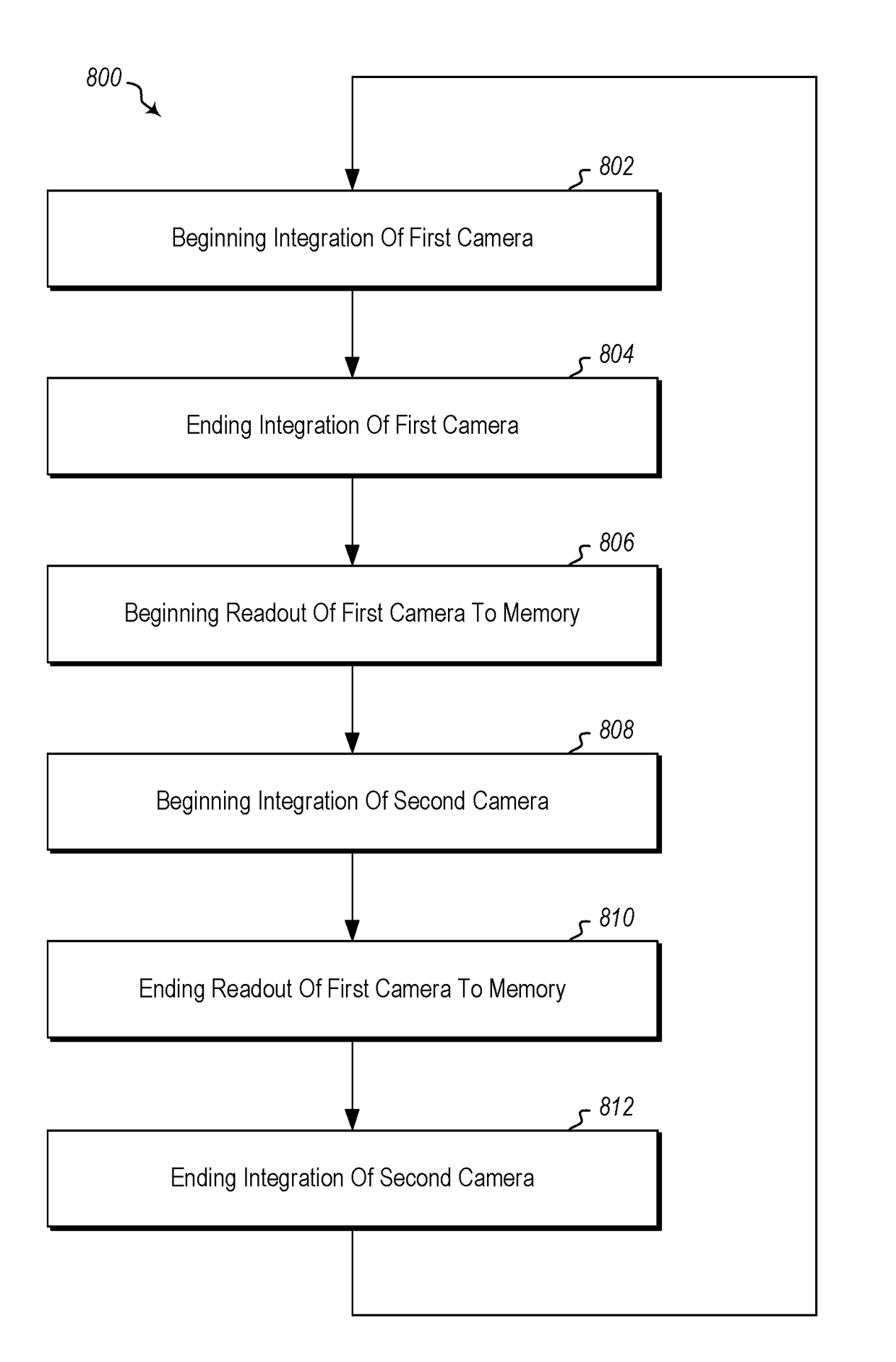
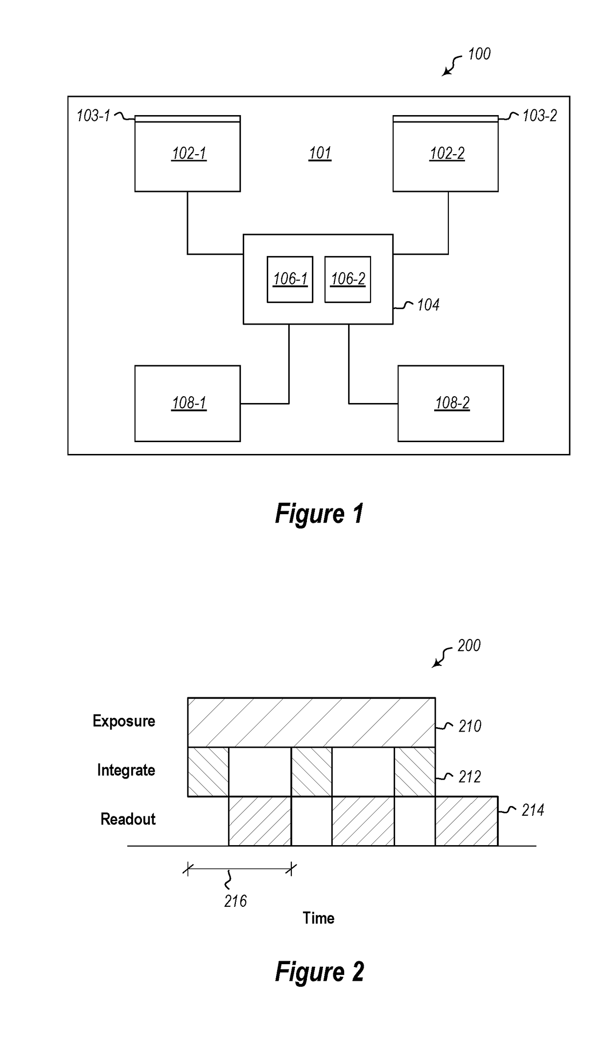
The present invention is about a system and method for 3D imaging using multiple cameras. The system includes a timing control block that synchronizes the communication of the cameras with each other and with external timers. The method involves starting the first camera's integration time and reading out the first camera's frames to memory. Then, the second camera's integration time is started, and the first camera's frames are read out to memory. This process is repeated for the next cameras until the last camera's frames are read out. The method also allows for aligning the cameras' schedules to avoid overlapping frames. The technical effect of this invention is to enable precise synchronization and alignment of multiple cameras, which can improve the accuracy and efficiency of 3D imaging.

Problems solved by technology

However, different active IR imaging systems operating concurrently can result in cross-contamination between the sensors.
If a second source is emitting a second output light, the TOF calculations can be distorted, resulting in incorrect depth calculations.
Optical interference can also result in unwanted signal / noise in the IR image.

Method used


Image

  • Systems and methods for interleaving multiple active camera frames
  • Systems and methods for interleaving multiple active camera frames
  • Systems and methods for interleaving multiple active camera frames

Examples


Embodiment Construction

[0023]Disclosed embodiments include improved imaging systems, as well as devices, systems, and methods for improving operating multiple active IR camera modules in a HMD for VR / AR applications.

[0024]With regard to the following disclosure, it will be appreciated that in the development of the disclosed embodiment(s), as in any engineering or design project, numerous embodiment-specific decisions will be made to achieve the developers' specific goals, such as compliance with system-related and business-related constraints, which may vary from one embodiment to another. It will further be appreciated that such a development effort might be complex and time consuming, but would nevertheless be a routine undertaking of design, fabrication, and manufacture for those of ordinary skill having the benefit of this disclosure.

[0025]Disclosed embodiments include, but are not limited to, head mounted displays that have multiple active IR imaging systems supporting depth (e.g., had tracking and ...


PUM


Abstract

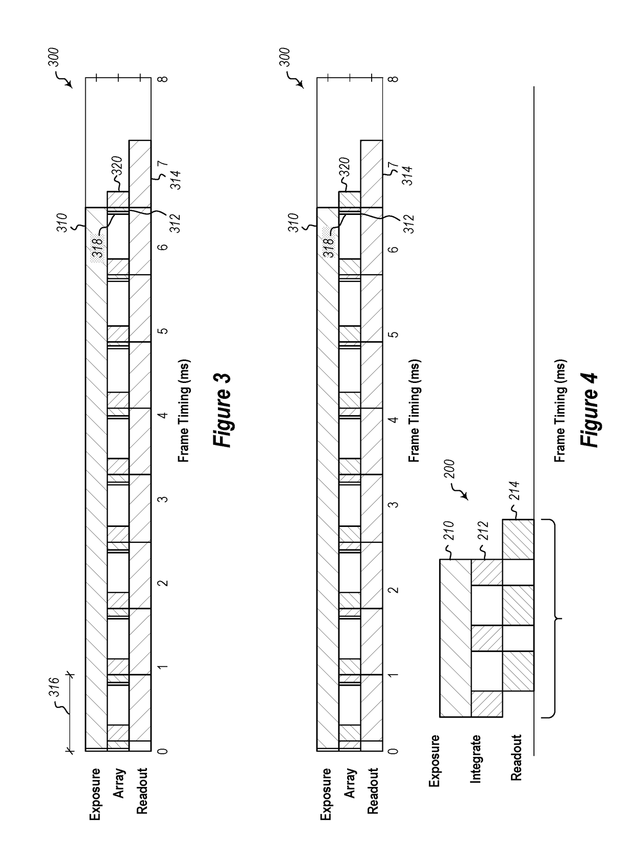
A system for three-dimensional imaging includes a plurality of three-dimensional imaging cameras. A first camera and a second camera may have integration times that are interleaved with the readout time of the other camera to limit interference while increasing framerate and throughput.

Description

CROSS-REFERENCE TO RELATED APPLICATIONS[0001]N / ABACKGROUNDBackground and Relevant Art[0002]Three-dimensional (3D) imaging systems are configured to identify and map a target based on light that is reflected from the target. Many of these imaging systems are configured with a light source that is configured to emit light towards the target and a photoreceptor to receive the light after it is reflected back from the target.[0003]Other active illuminated IR imaging systems may perform functions such as night vision, hand tracking, iris recognition, or eye tracking.[0004]Some imaging systems (i.e., time-of-flight imaging systems) are capable of identifying the distances and positions of objects within a target environment at any given time by measuring the elapsed time between the emission of light from the light source and the reception of the light that is reflected off of the objects.[0005]Other imaging systems (e.g., structured light systems) measure the distortion or displacement o...

Claims


Application Information

Patent Timeline
IPC IPC(8): H04N13/02G06K9/00G01S17/87G01S17/894
CPCG06K9/00604H04N13/254H04N13/296H04N2213/001G01S17/87G01S7/4811G01S17/894G06V40/19
Inventor ROSS, JONATHAN KENTPRICE, RAYMOND KIRKJAIN, PREETIKA
Owner MICROSOFT TECH LICENSING LLC
Learn More