

Heart rate detecting module and method
- Summary
- Abstract
- Description
- Claims
- Application Information
AI Technical Summary
Benefits of technology
Problems solved by technology
Method used
Image

Examples
first embodiment
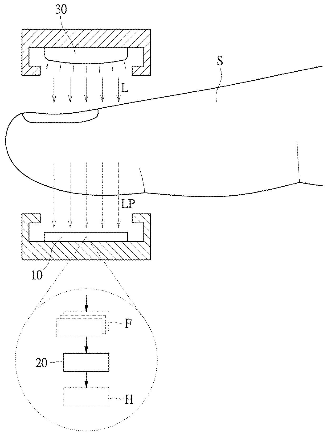
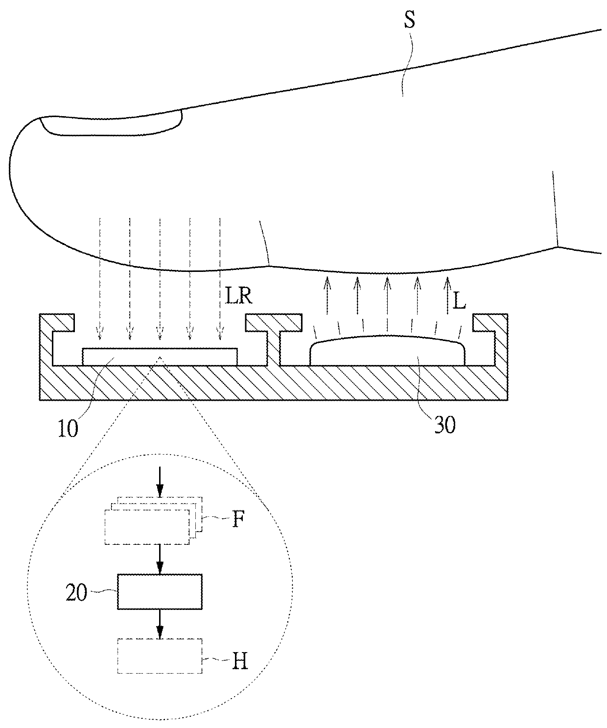
[0023]Please refer to FIG. 1, FIG. 2 and FIG. 4. FIG. 1 shows a schematic view of a heart rate detecting module of the first embodiment about a light passing through a subject in the instant disclosure, FIG. 2 shows a schematic view of a heart rate detecting module of the first embodiment about a light being reflected from a subject in the instant disclosure, and FIG. 4 shows a schematic view of an image sensor of the first embodiment in the instant disclosure. As shown in FIG. 1, the heart rate detecting module M of this embodiment includes an image sensor 10, a processor 20 and a light source 30. However, in other embodiments, the heart rate detecting module M may include a plurality image sensors 10, processors 20 and light sources 30, the number of the image sensor 10, the processor 20 and the light source 30 can be adjusted depending on requirements. In more details of FIG. 1, the image sensor 10 includes a sensor array which contains a plurality of pixels and is used to genera...
second embodiment
[0034]A heart rate detecting module M of the second embodiment in this instant disclosure includes an image sensor 10 and a processor 20. The image sensor 10 generates a plurality of laser speckles according to a laser light from a subject S. The processor 20 outputs a heart rate value H based on a change of at least one displacements of the plurality of laser speckles.
[0035]Please refer to FIG. 7. FIG. 7 shows a flowchart of a heart rate detecting method of the second embodiment in this instant disclosure. The heart rate detecting method of the second embodiment is a speckle pixel positioning method. Specifically, it includes the following steps, as shown in steps S701 to S711 in FIG. 7, a heart rate detecting method of the second embodiment in this instant disclosure includes the following steps. Firstly, in step S701 and step S703, a light source 30 is used to emit a laser light toward to a subject S, then an image sensor 10 receives the laser light passing through or reflected f...
PUM
 Abstract
Description
Claims
Application Information