Receiving end light power on-line detection device and implementation method thereof

A technology of detection device and implementation method, applied in transmission monitoring/test/fault measurement system, electromagnetic wave transmission system, electrical components, etc., can solve the problem of increased hardware cost and system complexity, inability to guarantee measurement accuracy, sampling signal noise impact, etc. problems, to reduce detection noise, facilitate diagnosis and maintenance, and control hardware costs

Active Publication Date: 2015-02-18
GUODIAN NANJING AUTOMATION
View PDF3 Cites 0 Cited by
  • Summary
  • Abstract
  • Description
  • Claims
  • Application Information

AI Technical Summary

Problems solved by technology

This can lead to a dramatic increase in hardware cost and system complexity
And due to the introduction of more noise, the measurement accuracy cannot be guaranteed
[0008] In addition to the above problems, since the modulation method used in optical fiber communication is the optical intensity modulation of incoherent light with noise characteristics, the transmission of digital signals is realized through optical pulses generated by optical switches. Therefore, the optical power detection at the receiving end still has The following technical problems need to be solved: 1) Selection of sampling point: If the sampling point falls on the "0" of optical pulse modulation, the optical power reflected by the obtained sampling information is almost 0, and it is impossible to distinguish whether it is caused by sampling or due to fiber channel 2) Noise effect on the sampling signal: Even if the sampling point falls on the "1" of the optical pulse modulation, due to the noise characteristics of the optical fiber channel, can the obtained optical pulse sampling information truly reflect the optical power

Method used


Image

  • Receiving end light power on-line detection device and implementation method thereof
  • Receiving end light power on-line detection device and implementation method thereof
  • Receiving end light power on-line detection device and implementation method thereof

Examples


Embodiment Construction

[0031] In order to make the purpose, technical solution and advantages of the present invention clearer, the present invention will be further described in detail below in conjunction with the accompanying drawings.

[0032]The hardware device and the online detection method of optical power at the receiving end designed by the present invention are to realize the automation of optical fiber channel monitoring in the power system, overcome the influence of communication interruption caused by current manual measurement, improve the reliability of the system, and save system maintenance cost.

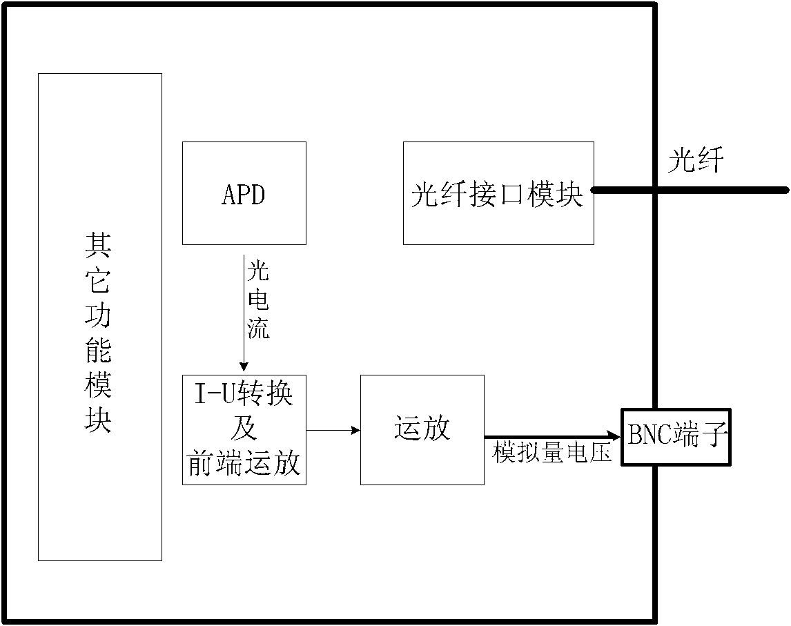
[0033] A. Hardware device and connection description

[0034] 1) The improved ONU module is based on the general ONU module, which changes the receiving function part of the general ONU module, see the attached figure 1 . The general ONU module uses a photoelectric conversion diode APD for optical pulse reception: APD converts optical pulses into current, and the magnitude of this c...


PUM


Abstract

The invention discloses a receiving end light power on-line detection device and an implementation method thereof. The receiving end light power on-line detection device comprises a universal ONU (Optical Network Unit) module and a data acquisition and processing module, wherein the universal ONU module comprises a photoelectric conversion circuit and an operational amplifying circuit; and the device is characterized in that: an external BNC (Bayonet Nut Connector) terminal is additionally arranged on the universal ONU module and is connected with an output end of the operational amplifying circuit. In the invention, real-time on-line monitoring of an optical fiber channel state can be realized under the condition of normal communication of an optical fiber communication system.

Description

technical field [0001] The invention relates to the field of optical fiber communication in power system applications, in particular to a device and implementation method for on-line detection of optical power at a receiving end. Background technique [0002] PON (Passive Optical Network, Passive Optical Network) system is more and more widely used in modern production and life due to its characteristics of high speed, high bandwidth, long transmission distance and low cost. The PON system consists of the following parts: ONU (Optical Network Unit, Optical Network Unit), ODN (Optical Distribution Network, Optical Distribution Network) and OLT (Optical Line Terminal, Optical Line Terminal). The direction of data direction from OLT to ONU is the downlink direction, and vice versa is the uplink direction. [0003] The PON system is based on WDM (Wavelength Division Multiplexing) technology, and uses different light waves to transmit uplink and downlink data respectively. T...

Claims


Application Information

Patent Timeline
Patent Type & Authority Patents(China)
IPC IPC(8): H04B10/07H04B10/071H04B10/079
Inventor 刘亮徐大可张雷杨春瑜蔡一磊
Owner GUODIAN NANJING AUTOMATION
Why Eureka
Try Eureka