Water quality monitoring system and method

a sensor system and water quality technology, applied in the field of water quality sensor system and method of monitoring water quality, can solve the problems of not being able to provide real-time data regarding water quality characteristics, not being able to account for contamination that may occur, and not being able to d

Inactive Publication Date: 2018-09-20
RICHTER CHRISTOPHER ROBERT
View PDF3 Cites 16 Cited by
  • Summary
  • Abstract
  • Description
  • Claims
  • Application Information

AI Technical Summary

Benefits of technology

[0007]It would therefore be desirable to have a low-cost system and method capable of analyzing and monitoring characteristics of a given medium in real time at a remote location relative to the monitored medium.

Problems solved by technology

While these sensor systems monitor characteristics of the water quality as it leaves the water supplier, the sensor systems cannot account for contamination that may occur as the water travels between the water supplier and the end user.
While these filtering devices improve the water quality from the water supply network, the filtering devices typically do not include integrated water sensors, cannot detect an increase in contaminants in the incoming water supply that may not be completely removed in the filtering device, and do not provide real-time data regarding the water quality characteristics that is accessible to a user remotely located relative to the filtering device.
Due to their high cost, these types of sensor systems are cost prohibitive for residential applications.
Another factor that contributes to the relative high cost of water sensor systems is the incremental cost associated with analyzing different types of water characteristics.
The greater the desired detection functionality of the sensing device, the higher the total cost of the system becomes as the inclusion of each sensor and associated processor incrementally increases the total sensor cost.
Adding more sensors to the system also increases the overall size of the device, as the device must be configured with a dedicated input port corresponding to each sensor.

Method used


Image

  • Water quality monitoring system and method
  • Water quality monitoring system and method
  • Water quality monitoring system and method

Examples


Embodiment Construction

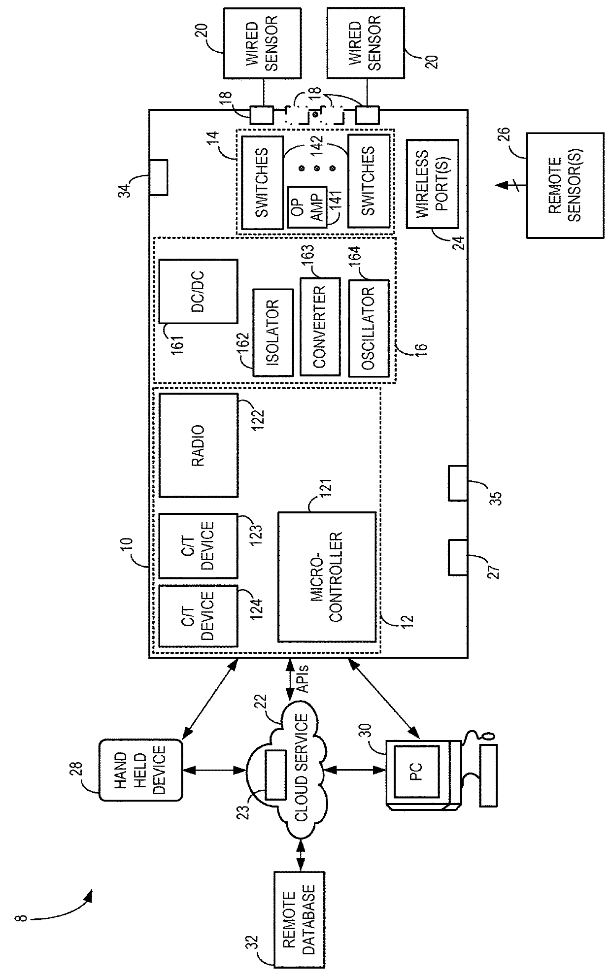
[0027]Embodiments of the disclosed system differ from typical prior art sensors that include all of the application specific sensors and associated data processing hardware directly on the sensing device. Unlike these prior art systems, the disclosed sensing device includes a hardware application program interface (API) that is controlled by a source external to the sensing device. This external processing source is described herein as a smart cloud management system or cloud-based processing service. However, it is contemplated that the external processing source may a computer, server, or other tangible device that includes processing capabilities similar to the cloud-based processing service described herein. The core software provided on the sensing device is a communication interface to the cloud service that permits the cloud service to manipulate the manner in which the device's hardware components acquire raw data from one or more attached wired or wireless sensors. Thus, th...


PUM

PropertyMeasurementUnit
frequenciesaaaaaaaaaa
frequencyaaaaaaaaaa
DFTaaaaaaaaaa

Abstract

A sensor system includes a sensing device that has a hardware application program interface (API) that is manipulated by a cloud service to measure certain parameters using a variety of attached sensors. The hardware API creates a communication interface between the sensing device and the cloud service that permits the cloud service to manipulate how the device's hardware components acquire raw data from one or more attached wired or wireless sensors. In certain embodiments data acquisition with the sensing device may be entirely cloud initiated permitting sensing device to be controlled to collect data using any type of sensor without the sensing device requiring any sensor-specific hardware or locally-stored programming specific to a particular type of sensor coupled to the device.

Description

CROSS-REFERENCE TO RELATED APPLICATION[0001]The present application is a non-provisional of, and claims priority to, U.S. Provisional Patent Application Ser. No. 62 / 472,887, filed Mar. 17, 2017, the disclosure of which is incorporated herein by reference in its entirety.BACKGROUND OF THE INVENTION[0002]The present invention relates generally to a water quality sensor system and method of monitoring water quality, more particularly, to a system and method that permits characteristics of an end-user water supply to be monitored in real time via a phone or tablet. The disclosed system and method also permits a user to monitor other aspects of their water system or any other medium in real-time via one or more different types of sensors coupleable to universal sensor inputs of a monitoring device.[0003]Existing devices used to determine water quality typically include one or more water quality meters or sensors that are inserted into the water supply network of the water supplier (e.g.,...

Claims


Application Information

Patent Timeline
Patent Type & Authority Applications(United States)
IPC IPC(8): H04Q9/00G01N27/06G01N33/18
CPCH04Q9/00G01N27/06G01N33/1886H04Q2209/84H04Q2209/40
Inventor RICHTER, CHRISTOPHER ROBERTRICHTER, JR., ROBERT GUSTAVEORTEGA, EDGAR ALEJANDRO DUARTE
Owner RICHTER CHRISTOPHER ROBERT
Why Eureka
Try Eureka