Machine tool system and clamping method

a technology of machine tools and clamping methods, applied in the field of machine tool systems, can solve the problems and achieve the effect of increasing the time of the machining cycl

Active Publication Date: 2018-09-27
FANUC LTD
View PDF0 Cites 1 Cited by
  • Summary
  • Abstract
  • Description
  • Claims
  • Application Information

AI Technical Summary

Benefits of technology

[0004]However, in the configuration described in Japanese Laid-Open Patent Publication No. 2015-209658, the workpiece has to be fixed (clamped) by a clamping device installed on the table after the workpiece is carried into the machining space. Further, when the clamping device is used, it is necessary to use a sensor or the like to confirm that the workpiece has been correctly clamped. Moreover, when unloading the machined workpiece to the outside of the processing machine, it is necessary to release (unclamp) the workpiece fixed by the clamp device. Thus, the clamping and unclamping by the clamping device ends up increasing the time of the machining cycle.

Problems solved by technology

Moreover, when unloading the machined workpiece to the outside of the processing machine, it is necessary to release (unclamp) the workpiece fixed by the clamp device.
Thus, the clamping and unclamping by the clamping device ends up increasing the time of the machining cycle.

Method used


Image

  • Machine tool system and clamping method
  • Machine tool system and clamping method
  • Machine tool system and clamping method

Examples


##al examples

VARIATIONAL EXAMPLES

[0050]The above embodiment may be modified as follows.

##al example 1

Variational Example 1

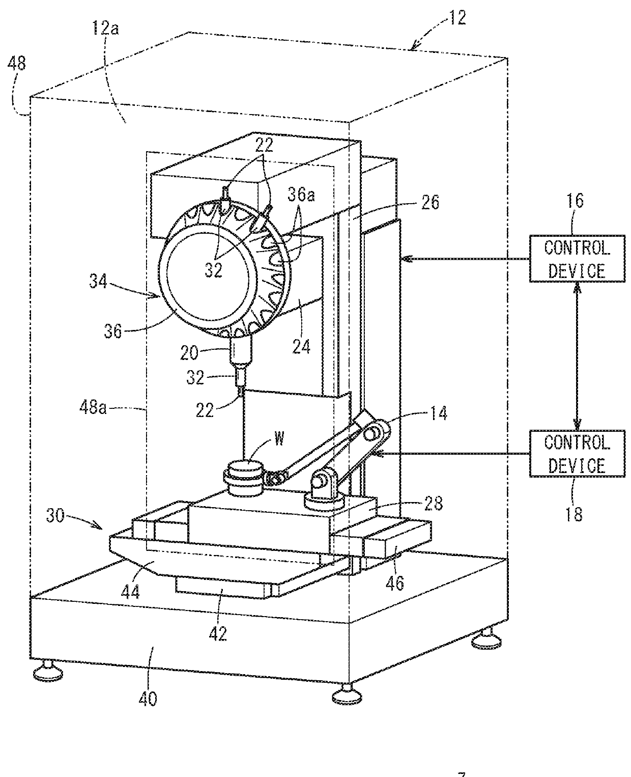
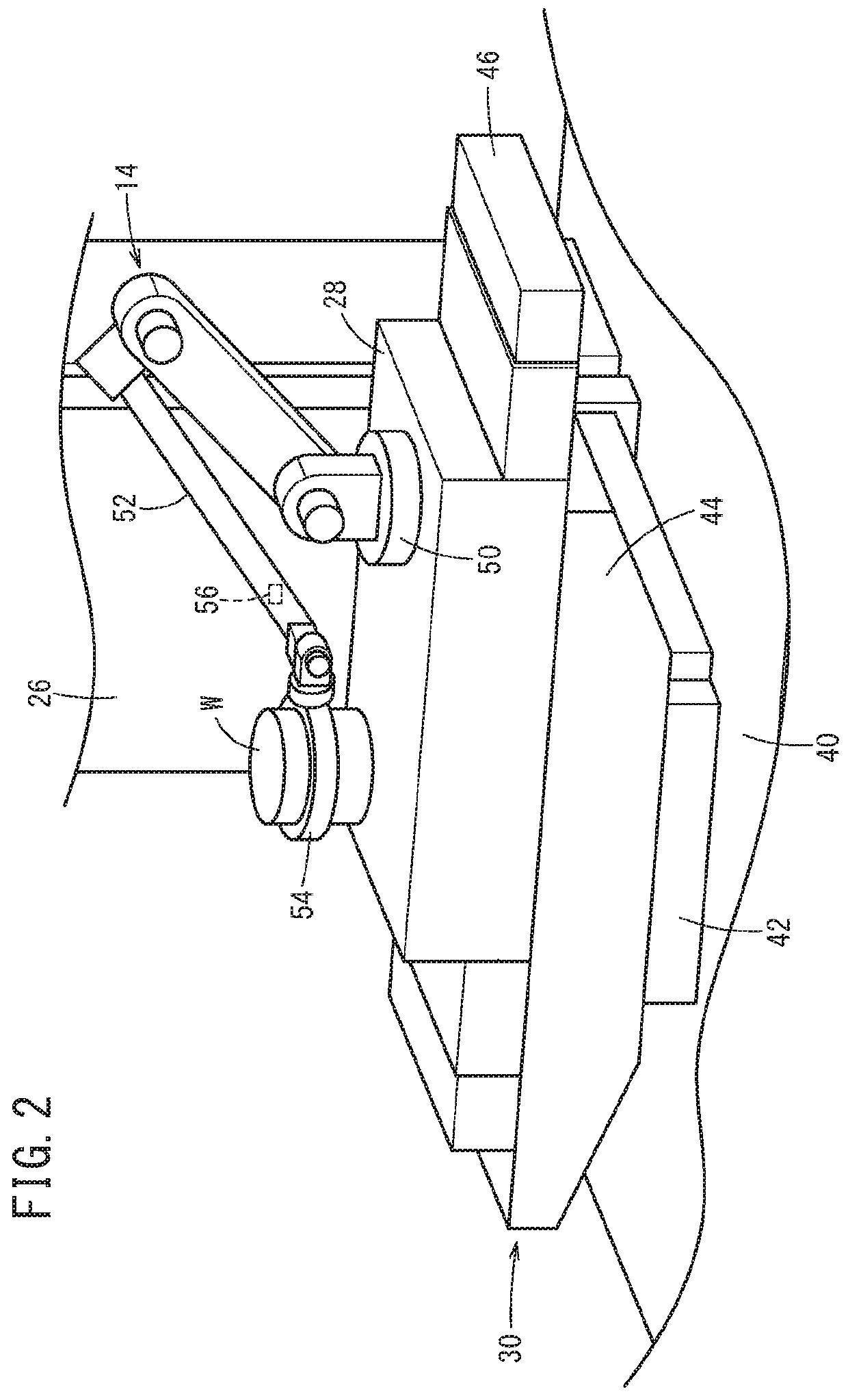
[0051]In the above embodiment, though the workpiece W is clamped by the robot 14, there occur cases in which it becomes difficult for the robot 14 to accurately clamp the workpiece W due to excessive machining torque or excessive cutting speed. As a countermeasure against such a situation, in variational example 1, a vibration detector 56 for detecting vibration may be provided for the robot 14 (see FIG. 2). The vibration detector 56 is to detect the vibration caused by the machining of the workpiece W with the tool 22. The machine tool 12 (specifically, the control device 16) may be configured to change at least one of the machining torque and the cutting feed speed of the tool 22 in accordance with the vibration detected by the vibration detector 56. For example, when the detected level of vibration is equal to or greater than a threshold, the machine tool 12 reduces the machining torque or slows down the cutting feed speed in order to suppress the vibration d...

##al example 2

Variational Example 2

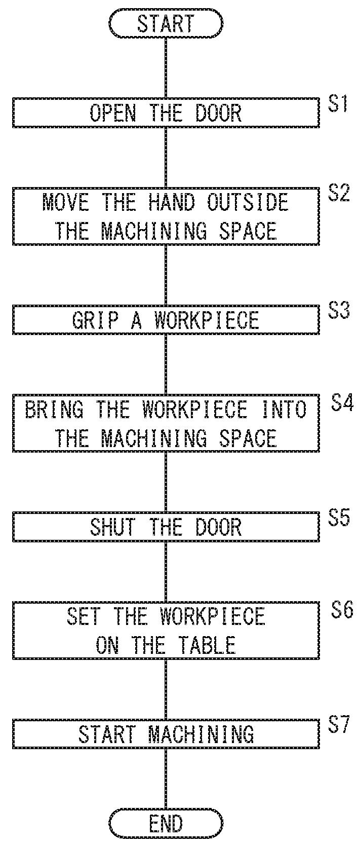
[0052]Though in the above embodiment the robot 14 is adapted to load, place, clamp, and unload the workpiece W, a transport device may be provided to carry in and out the workpiece W. That is, the transport device may load a blank workpiece W into the machining space 12a and unload the machined workpiece W to the outside of the machining space 12a. In this case, the robot 14 grips the blank workpiece W brought in by the transport device, places the blank workpiece W on the table 28, and hands over the machined object W to the transport device.

[Technical Idea Obtained from the Embodiment]

[0053]Technical ideas that can be grasped from the above embodiment and variational examples 1 and 2 will be described hereinbelow.

[0054]A machine tool system (10) includes: a machine tool (12) configured to machine a workpiece (W) set on a table (28) using a tool (22) attached to a spindle (20); and a robot (14) configured to grip the workpiece (W). The robot (14) is installed o...


PUM


Abstract

A machine tool system includes: a machine tool for machining a workpiece set on a table using a tool attached to a spindle; and a robot for gripping the workpiece. The robot is installed on the table and performs a setting operation for setting the workpiece on the table and a clamping operation for clamping the workpiece.

Description

CROSS-REFERENCE TO RELATED APPLICATION[0001]This application is based upon and claims the benefit of priority from Japanese Patent Application No. 2017-060554 filed on Mar. 27, 2017, the contents of which are incorporated herein by reference.BACKGROUND OF THE INVENTIONField of the Invention[0002]The present invention relates to a machine tool system having a clamping function for clamping a workpiece, as well as a clamping method.Description of the Related Art[0003]Japanese Laid-Open Patent Publication No. 2015-209658 discloses a configuration in which an articulated robot arranged outside a processing machine is used to load a blank workpiece into a processing machine and unload the finished workpiece out of the processing machine.SUMMARY OF THE INVENTION[0004]However, in the configuration described in Japanese Laid-Open Patent Publication No. 2015-209658, the workpiece has to be fixed (clamped) by a clamping device installed on the table after the workpiece is carried into the mac...

Claims


Application Information

Patent Timeline
Patent Type & Authority Applications(United States)
IPC IPC(8): B23Q7/04B25J9/00B25J9/16B25J19/02B25J15/00B25J11/00
CPCB23Q7/047B25J9/0096B25J9/1612B25J9/1679B25J19/02B25J15/0038B25J11/005B23Q7/046B23Q37/00B23Q11/0891B23Q2220/002G05B2219/39105Y02P90/02
Inventor WATANABE, RIKIZOU
Owner FANUC LTD
Why Eureka
Try Eureka