Flight vehicle engine with finned inlet

a technology for flight vehicles and engines, applied in machines/engines, efficient propulsion technologies, combustion air/fuel air treatment, etc., can solve the problems of large internal volume, complex and occupying a significant amount of space, and causing performance degradation

Active Publication Date: 2018-09-27
RAYTHEON CO
View PDF6 Cites 4 Cited by
  • Summary
  • Abstract
  • Description
  • Claims
  • Application Information

AI Technical Summary

Benefits of technology

[0023]According to still another aspect of the invention, a method of operating a flight vehicle engine includes: using a fin in an inlet of the engine to cause the boundary layer to aggregate then separate from the surface as

Problems solved by technology

These systems are often complex and occupy a significant amount of i

Method used


Image

  • Flight vehicle engine with finned inlet
  • Flight vehicle engine with finned inlet
  • Flight vehicle engine with finned inlet

Examples


Embodiment Construction

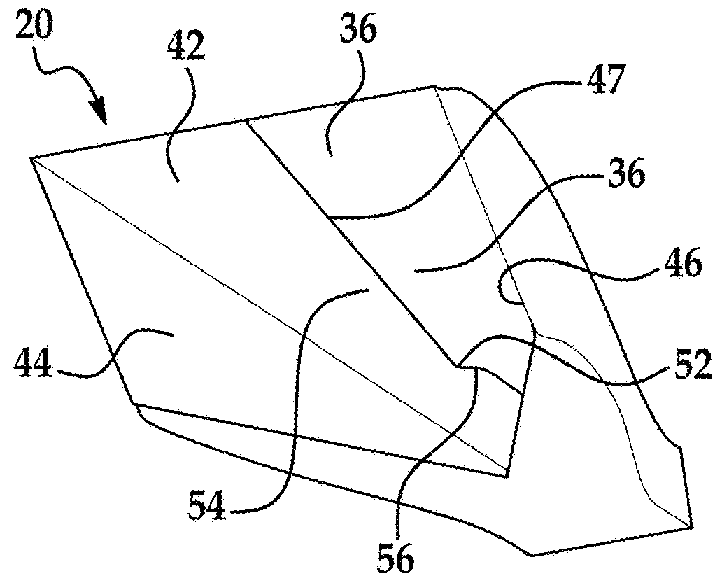
[0037]An air inlet for a flight vehicle engine includes at least one fin, at least partially upstream of a throat of the engine. The fin protrudes into a flow channel, extending beyond a boundary layer into the main airstream in the inlet. The fin causes mixing in the flow, mixing high-momentum flow into areas of the flow channel with low-momentum flow. The fin may have a width and / or height that varies along its length in the flow direction, which may allow it to shape the flow around it in predictable ways, without resulting in excessive drag.

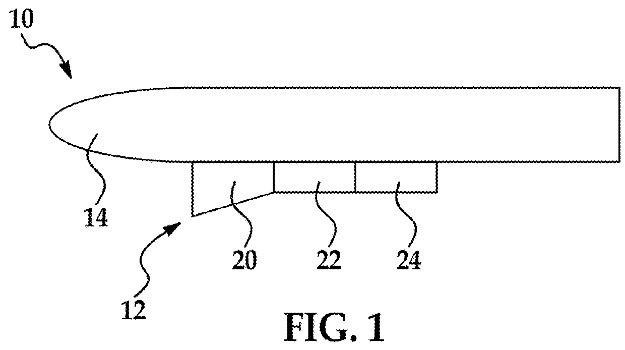
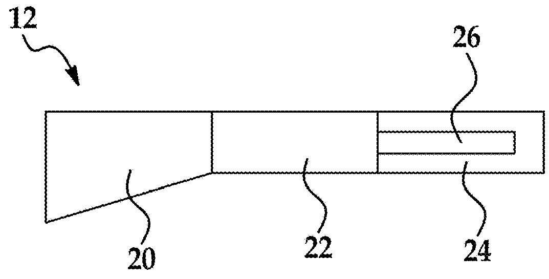
[0038]FIG. 1 schematically shows an air vehicle 10 that is powered by an engine 12 that is mechanically coupled to a fuselage 14. The air vehicle 10 may be a missile, an unmanned aircraft (an unmanned aerial vehicle or UAV) or a manned aircraft. The air vehicle 10 may have any of a variety of sizes, and any of a variety of operating conditions. In much of the description below the air vehicle 10 is described in terms of a hypersonic air vehic...


PUM


Abstract

An air inlet for a flight vehicle engine includes at least one fin, at least partially upstream of a throat of the engine. The fin protrudes into a flow channel, extending beyond a boundary layer into the main airstream in the inlet. The fin causes mixing in the flow, bringing high-momentum flow into areas of the flow channel containing low-momentum flow by aggregating the boundary layer and causing it to lift from the surface. The fin may have a width and/or height that varies along its length in the flow direction, which may allow it to shape the flow around it in predictable ways, without resulting in excessive drag.

Description

FIELD OF THE INVENTION[0001]The invention is in the field of engines for flight vehicles such as airplanes or missiles.DESCRIPTION OF THE RELATED ART[0002]High-speed air-breathing engines, such as ramjets and scramjets, include inlets that capture and compress air to be used in combustion. The air that passes through the inlet is then directed downstream to an isolator, and from there to a combustor.[0003]There has been a general need to manage the flow within the inlet, particularly the boundary layer that forms along the walls of the inlet. Management of a thick boundary layer from a high-speed inlet compression surface usually involves a large amount of mass flow removal via a boundary layer diverter, boundary layer bleed, or placement of a bump or bumps in the flow ahead of the inlet. These systems are often complex and occupy a significant amount of internal volume and can produce a substantial penalty in performance.SUMMARY OF THE INVENTION[0004]A flight vehicle engine inlet i...

Claims


Application Information

Patent Timeline
IPC IPC(8): F02K7/10B64D33/02B64D27/16
CPCF02K7/10B64D33/02B64D27/16F05D2250/14B64D2033/026F05D2220/10F05D2250/51B64D2033/0226B64C2230/26B64C30/00F02C7/04Y02T50/10Y02T50/60F02K7/00
Inventor O'BRIEN, TIMOTHY F.MALO-MOLINA, FAURECONNERS, TIMOTHY RAYMOND
Owner RAYTHEON CO
Why Eureka
Try Eureka