Piston ring with varying apex lines

a technology of apex line and piston ring, which is applied in the direction of engine components, trunk pistons, engine seals, etc., can solve the problems of short distribution of lubricant, great challenges in ensuring the quality of lubrication, and reduce the amount of lubricant needed, and achieve uniform distribution

Inactive Publication Date: 2018-09-27
FEDERAL MOGUL BURSCHEID
View PDF8 Cites 3 Cited by
  • Summary
  • Abstract
  • Description
  • Claims
  • Application Information

AI Technical Summary

Benefits of technology

The invention provides a piston ring that reduces oil consumption, improves lubrication, and is cost-effective. The ring shape creates hydrodynamic pressure, which leads to a more uniform distribution of lubricant. This results in a reduction of lubricant usage and improved efficiency.

Problems solved by technology

If one considers that modern, large-volume two-stroke ship engines are operated at a speed of approximately 50 rpm to 250 rpm with a stroke of up to 2500 mm, the time span available for the supply of the lubricant and the distribution of the supplied lubricant is short and presents great challenges in ensuring the quality of the lubrication.

Method used


Image

  • Piston ring with varying apex lines
  • Piston ring with varying apex lines
  • Piston ring with varying apex lines

Examples


Embodiment Construction

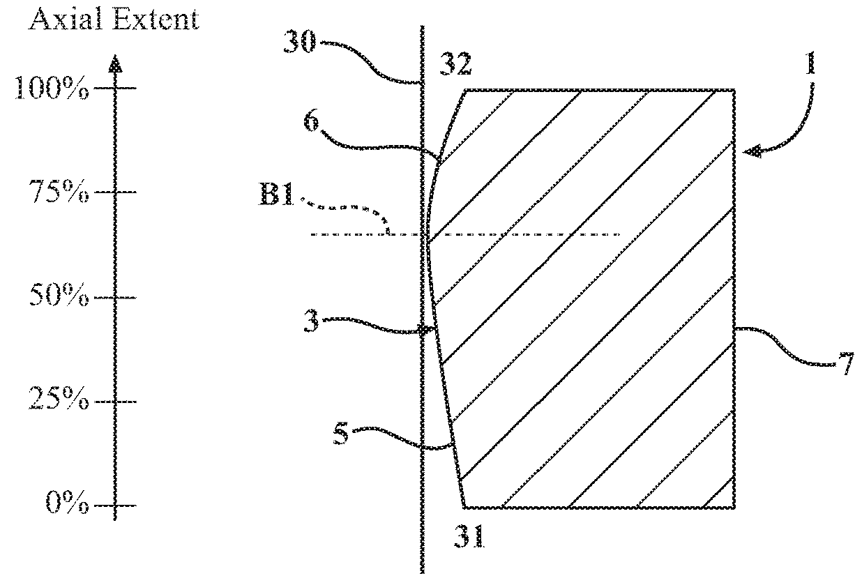
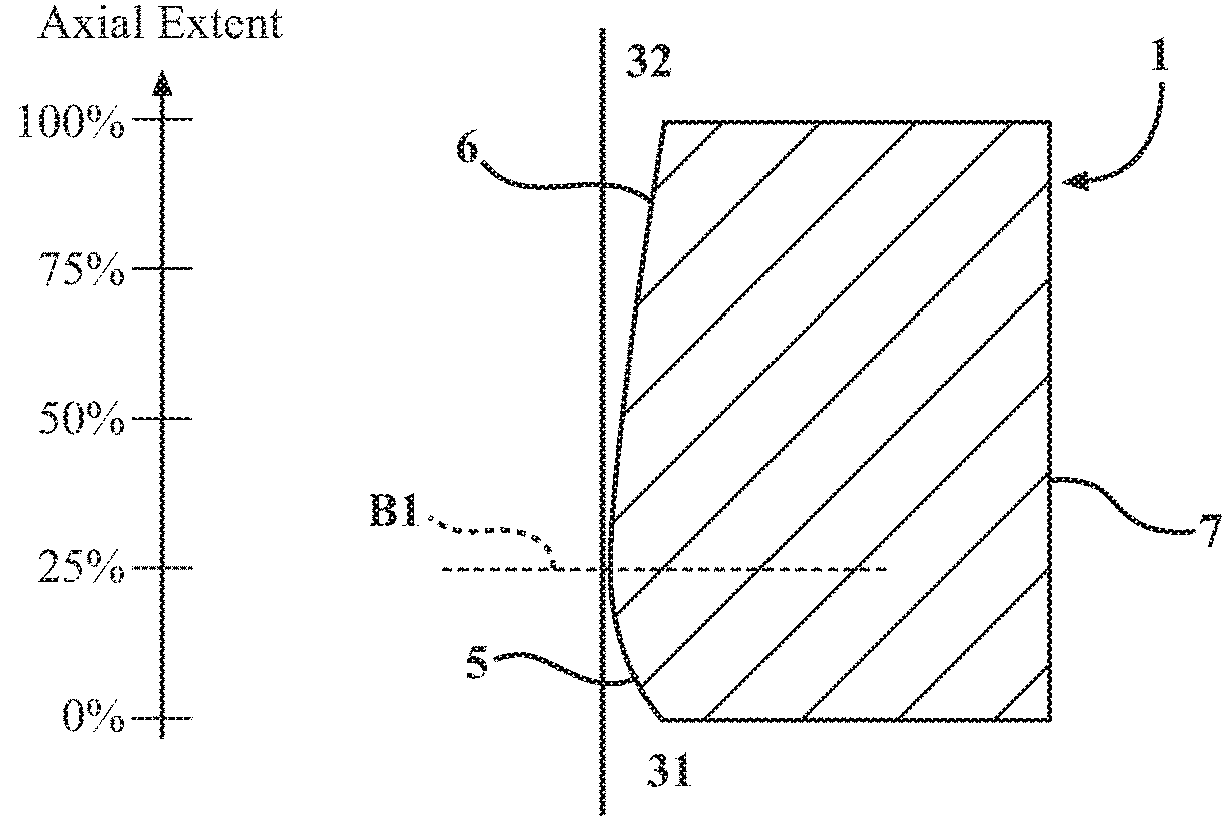
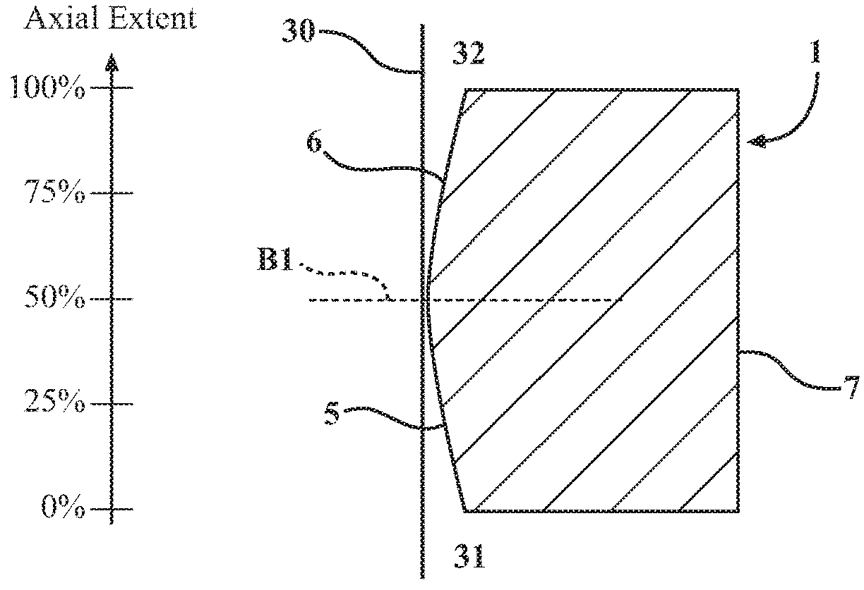
[0031]FIGS. 1(a) to 1(c) show (radial) cross sections, which are spaced apart from each other in the circumferential direction, through a piston ring 1 according to the invention.

[0032]The piston ring 1 according to the invention, which is shown in FIG. 1 and preferably acts as a compression and oil control ring at the same time, has an outer profiled side that faces away from the combustion chamber, i.e. a profiled running face 3 of the piston ring 1, a flank 5 that faces the combustion chamber 31, a flank 6 that faces the oil chamber 32 and an inner circumferential face 7. The piston ring 1 is made of a monolithic piece of metal, such as steel or an alloy steel.

[0033]FIG. 5 shows the piston ring 1 installed in the ring groove of a piston 33 in a two-stroke, diesel fueled, compression-ignition engine 34, such as for use in a ship. The ring groove has a top wall and a bottom wall, and the flanks 5, 6 of the piston ring 1 extend parallel to the top and bottom walls.

[0034]FIG. 6 shows...


PUM


Abstract

A piston ring having an outer running face, two flanks and an inner circumferential face is provided. The running face has profiling. The profile of the running face is substantially convexly curved and has an apex. The axial position of the apex varies periodically in the circumferential direction.

Description

CROSS REFERENCE TO RELATED APPLICATIONS[0001]This U.S. Continuation-in-Part Patent Application claims the benefit of U.S. patent application Ser. No. 14 / 441,969, filed Sep. 23, 2013 entitled “Piston Ring With Varying Apex Lines,” which claims priority to PCT Patent Application No. PCT / EP2013 / 069692, filed Sep. 23, 2013, entitled “Piston Ring With Varying Apex Lines,” which claims priority to German Patent Application No. 10 2012 220 464.4, filed Nov. 9, 2012, entitled “Piston Ring With Varying Apex Lines,” the entire disclosures of these applications being considered part of the disclosure of this application and hereby incorporated by reference.BACKGROUND OF THE INVENTION1. Field of the Invention[0002]The present invention relates to a piston ring for an internal combustion engine or for a compressor, in particular a piston ring having an apex line that is arranged on the running face running in the circumferential direction and varies periodically in the axial direction.2. Related...

Claims


Application Information

Patent Timeline
IPC IPC(8): F16J9/20F16J9/26F16J1/08
CPCF16J9/206F16J9/26F16J1/08F16J15/3244
Inventor MITTLER, RICHARDNATHEM, FRANK
Owner FEDERAL MOGUL BURSCHEID
Why Eureka
Try Eureka