Correction of multipath interference in time of flight camera depth imaging measurements

a technology of depth imaging and multipath interference, which is applied in the direction of instruments, measurement devices, and using reradiation, etc., can solve the problems of multipath interference in the time of flight camera system, high accuracy of depth estimates, and corrupted sensor measurements

Inactive Publication Date: 2018-09-27
MICROSOFT TECH LICENSING LLC
View PDF0 Cites 23 Cited by
  • Summary
  • Abstract
  • Description
  • Claims
  • Application Information

AI Technical Summary

Benefits of technology

[0004]Systems and methods for correcting multipath interference in determining distances to features in a scene to address the challenges above are disclosed. The system may include a frame buffer arranged to receive, for a frame captured by a time of flight camera, depth imaging measurements for each of a plurality of pixels arranged to measure light received from respective portions of the scene. The system may also include a target portion identifier module configured to identify a plurality of target portions of the scene, each target portion corresponding to portions of the scene measured by two or more of the pixels. The system may also include a target surface generator configured to simulate a plurality of target surfaces, including determining, for each target portion included in the plurality of target portions, a position and an orientation for a respective simulated target surface based on the depth imaging measurements for the measured portions of the scene included in the target portion. The system may also include a reflector selection module configured to select one half or fewer of the plurality of target surfaces as a first plurality of reflector surfaces and, for each target surface included in the target surfaces, select a second plurality of reflector surfaces from the first plurality of reflector surfaces. The system may also include a light transport simulation module configured to, for each target surface included in the target surfaces, simulate, for each reflector surface selected by the reflector selection module for the target surface, a multipath reflection of light emitted by the camera, reflected by the reflector surface to the target surface, and reflected by the target surface to the camera, to generate a simulated multipath response for the target surface. The system may also include a depth measurement correction generation module configured to generate a depth measurement correction for each target surface based on the simulated multipath response generated for the target surface by the light transport simulation module. The system may also include a distance calculation module configured to determine distances for the pixels based on the depth measurement corrections generated by the depth measurement correction generation module for the plurality of target surfaces.
[0005]This Summary is provided to introduce a selection of concepts in a simplified form that are further described below in the Detailed Description. This Summary is not intended to identify key features or essential features of the claimed subject matter, nor is it intended to be used to limit the scope of the claimed subject matter. Furthermore, the claimed subject matter is not limited to implementations that solve any or all disadvantages noted in any part of this disclosure.

Problems solved by technology

However, time of flight camera systems suffer from multipath interference.
This results in corrupted sensor measurements.
These corruptions do not look like ordinary noise, and can be quite large, resulting in highly inaccurate depth estimates.
Also, a gated time of flight camera, for example, may introduce structured, rather than unstructured, per-pixel noise.
Although there have been some previous realtime approaches, there are shortcomings in assumptions or generalizations about multipath interference and / or camera response to multipath interference that reduce the quality of the resulting corrections.
In addition to increasing an amount of reflected light received for a portion of a scene, multipath components are delayed relative to the direct component, due to their paths being longer.
Response characteristics for a light source may result in a waveform that deviates from an ideal sinusoid.
Due to such reduction in amplitude resulting in a weak signal, even for a direct component, along with other design considerations, it is impractical for a time of flight camera to directly measure the time delay Δt.
In general, the amount of photons received by a pixel in a single accumulation period does not result in a useful amount of charge being accumulated.
The depth imaging measurements generated by the time of flight camera 305 are contaminated by multipath interference which, left uncorrected, may lead to significant errors in estimated distances between the time of flight camera and portions of the scene.
Also, although in this approach none of the identified target areas overlap, other approaches may result in overlapping target portions.
In some circumstances, a target portion may later be removed for the identified plurality of target portions; for example, depth imaging measurements corresponding to a target portion may be determined to be unreliable.
The complexity of the light transport simulations is O(n2), which makes realtime multipath interference correction by simulating light transport between the much larger number of pixels impractical or impossible.
It is understood that this albedo may be inaccurate due to multipath interference
In some implementations, non-Lambertian (or specular) reflections from the reflector surface onto the target could also be simulated, although typically material properties for objects in the captured scene are unavailable for such simulations.

Method used


Image

  • Correction of multipath interference in time of flight camera depth imaging measurements
  • Correction of multipath interference in time of flight camera depth imaging measurements
  • Correction of multipath interference in time of flight camera depth imaging measurements

Examples


Embodiment Construction

[0018]In the following detailed description, numerous specific details are set forth by way of examples in order to provide a thorough understanding of the relevant teachings. However, it should be apparent that the present teachings may be practiced without such details. In other instances, well known methods, procedures, components, and / or circuitry have been described at a relatively high-level, without detail, in order to avoid unnecessarily obscuring aspects of the present teachings.

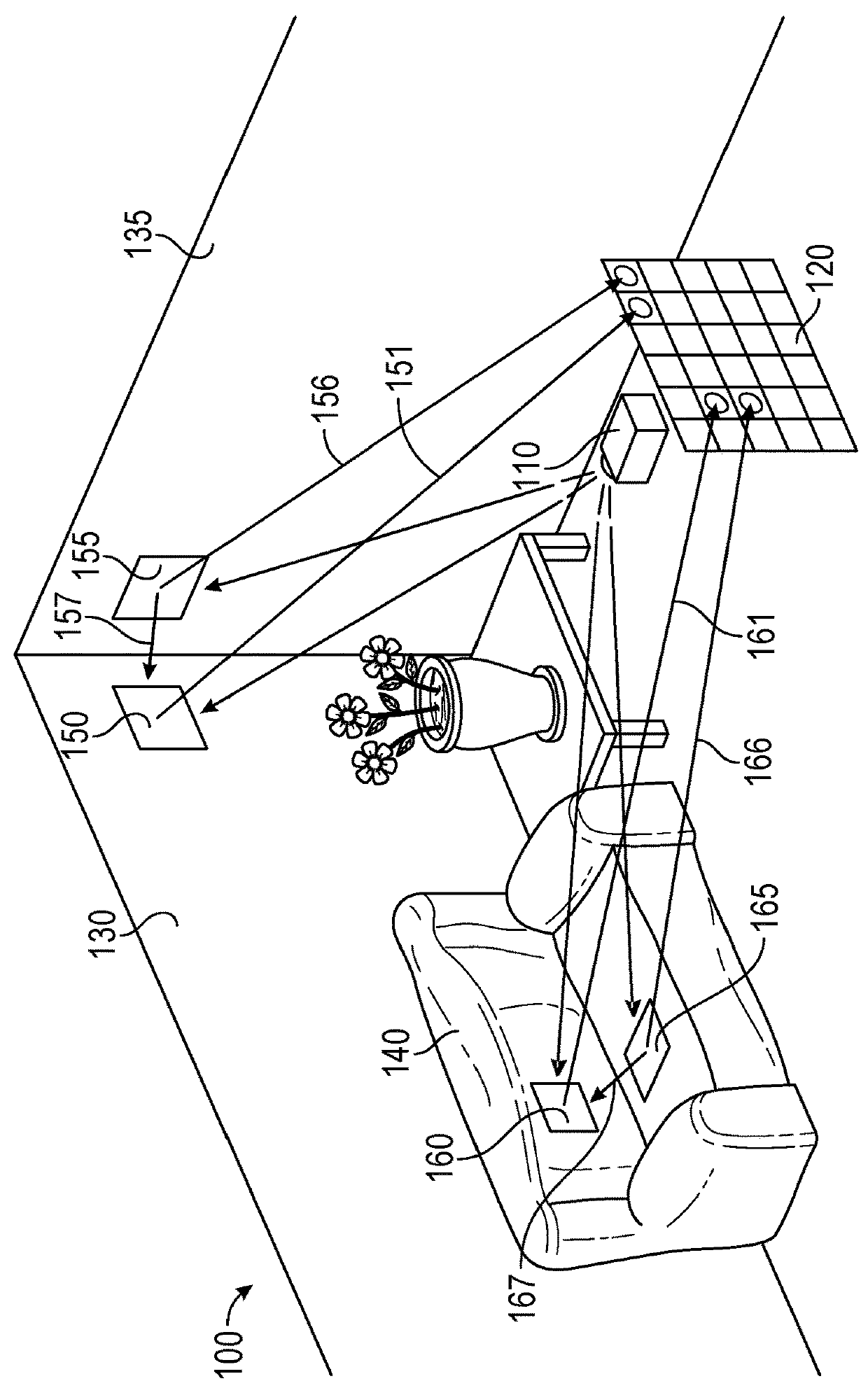
[0019]FIG. 1 illustrates an example of capturing depth imaging measurements using a time of flight depth camera, in which the depth imaging measurements include multipath interference. The time of flight depth camera includes, among other features, a light source 110 arranged to transmit light to a scene 100 within a field of view captured via pixel array 120. In some implementations, the light source 110 may be an incoherent light source, such as, but not limited to, a near-infrared light emitting ...


PUM


Abstract

A system for determining distances to features in a scene is disclosed. The system includes, among other features, a target portion identifier module, a target surface generator, a reflector selection module, a light transport simulation module, a depth measurement correction generation module, and a distance calculation module. The target portion identifier module is configured to identify a plurality of target portions of the scene. The target surface generator is configured to simulate a plurality of target surfaces. The reflector selection module is configured to select a first plurality of reflector surfaces from the plurality of target surfaces and a second plurality of reflector surfaces from the first plurality of reflector surfaces. The light transport simulation module is configured to, for each target surface included in the target surfaces, simulate a multipath reflection of light emitted by the camera, reflected by the reflector surface to the target surface, and reflected by the target surface to the camera, to generate a simulated multipath response for the target surface. The depth measurement correction generation module is configured to generate a depth measurement correction for each target surface based on the simulated multipath response. The distance calculation module is configured to determine distances for the pixels based on the depth measurement corrections.

Description

BACKGROUND[0001]Time of flight imaging is a type of depth sensing technology used in many computer vision applications such as object tracking and recognition, human activity analysis, hand gesture analysis, and indoor 3D mapping, amongst others. A time of flight camera system includes one or more light sources which emit rays of light into a scene, and a light sensor such as a camera. The time of flight system works by computing the time it takes a ray of emitted light to bounce off a surface and return to a camera at the system. This gives a measurement of the depth of the surface from the camera. Time of flight systems are generally able to achieve reasonable accuracy and operate in low illumination settings where they use light in the infrared spectrum.[0002]However, time of flight camera systems suffer from multipath interference. Where the emitted rays of light are sent out for each pixel, and since light can reflect off surfaces in myriad ways, a particular pixel may receive ...

Claims


Application Information

Patent Timeline
Patent Type & Authority Applications(United States)
IPC IPC(8): H04N13/02
CPCH04N13/207H04N13/25G01S11/00G01S17/42G01S17/18G01S17/894
Inventor SCHOENBERG, MICHAEL JOHNKUZHINJEDATHU, KAMAL RAMACHANDRANSMIRNOV, MIKHAILMESSER, CHRISTOPHER STEPHENGOURLAY, MICHAEL JASON
Owner MICROSOFT TECH LICENSING LLC
Why Eureka
Try Eureka