Linear motion guide unit

a technology of moving guide unit and guide surface, which is applied in the direction of linear bearings, shafts and bearings, bearings, etc., can solve the problems of small gap between the guide surface, high cost, and uneven rolling of the rollers, so as to reduce costs and reliably press the end surfaces of the rollers. , the effect of smooth rolling

Active Publication Date: 2018-10-04
NIPPON THOMPSON
View PDF0 Cites 1 Cited by
  • Summary
  • Abstract
  • Description
  • Claims
  • Application Information

AI Technical Summary

Benefits of technology

[0016]In the linear motion guide unit of the present invention, as mentioned above, the protrusion provided at each of opposite end portions of the retainer member made of resin of the retainer plate comes into contact with one end surfaces of the rollers to thereby press the other end surfaces of the rollers against the guide surface of the carriage. By this action, the opposite end surfaces of the rollers are pressed between the protrusion and the guide surface, whereby the inclined rollers are corrected in posture such that the axes of the rollers become orthogonal to the guide surface of the carriage, so that the rollers can be arrayed in a proper posture. That is, according to the present linear motion guide unit, the rollers having been inclined as a result of rolling in the no-load area of the circulating circuit are arrayed in such a posture that the axes of the rollers become orthogonal to the guide surface of the carriage, so that the rollers can be introduced in a proper posture into the load area. Therefore, there can be restrained scratchy sliding, early emergence of wear, fluctuations in sliding friction, and the generation of heat, which could otherwise result from skew. Further, according to the present linear motion guide unit, since by means of the inclined surfaces formed at the opposite end portions of the protrusion of the retainer member, the rollers can be gradually arrayed in such a posture that the axes of the rollers become orthogonal to the guide surface of the carriage, the rollers can smoothly roll in the circulating circuit. According to the present linear motion guide unit, when the rollers pass the protrusion of the retainer member, the protrusion is pressed against the end surfaces of the rollers through utilization of bending of the cantilevered retainer portions of the retainer member, so that the inclined rollers can be reliably corrected in posture and arrayed such that the axes of the rollers become orthogonal to the guide surface of the carriage. Since the present linear motion guide unit is configured as mentioned above, there is no need to raise the individual accuracies of components and to strictly control the gap between the rollers and the circulating circuit, so that costs can be reduced. Further, according to the present linear motion guide unit, the spring member is disposed between the cantilevered retainer portions at each of opposite end portions of the retainer member for urging the cantilevered retainer portions to elastically deform, whereby the protrusion can be reliably pressed against the end surfaces of the rollers. Since screwing the retainer plate to the carriage involves potential deformation of the resin retainer member of the retainer plate as a result of subjection to a fastening force of the fastening bolts, the frame members made of metal are disposed at screwing positions of the retainer member so as to fix the retainer plate to the carriage via the frame members. As a result, since the fastening force of the fastening bolts is not directly applied to the retainer member, deformation of the retainer member caused by screw engagement can be restrained.

Problems solved by technology

The inclined rolling rollers may cause the occurrence of skew in which the rollers roll while generating sliding friction.
However, in order to smoothly circulate the rollers, a small gap must exist between the end surfaces of the rollers and the guide surface.
However, such measures are costly.

Method used


Image

  • Linear motion guide unit
  • Linear motion guide unit
  • Linear motion guide unit

Examples


Embodiment Construction

[0035]The linear motion guide unit according to the present invention is applicable to relative sliding members used in various types of apparatus such as machine tools, semiconductor fabrication systems, and precision measuring apparatus.

[0036]An embodiment of the linear motion guide unit according to the present invention will next be described with reference to the drawings.

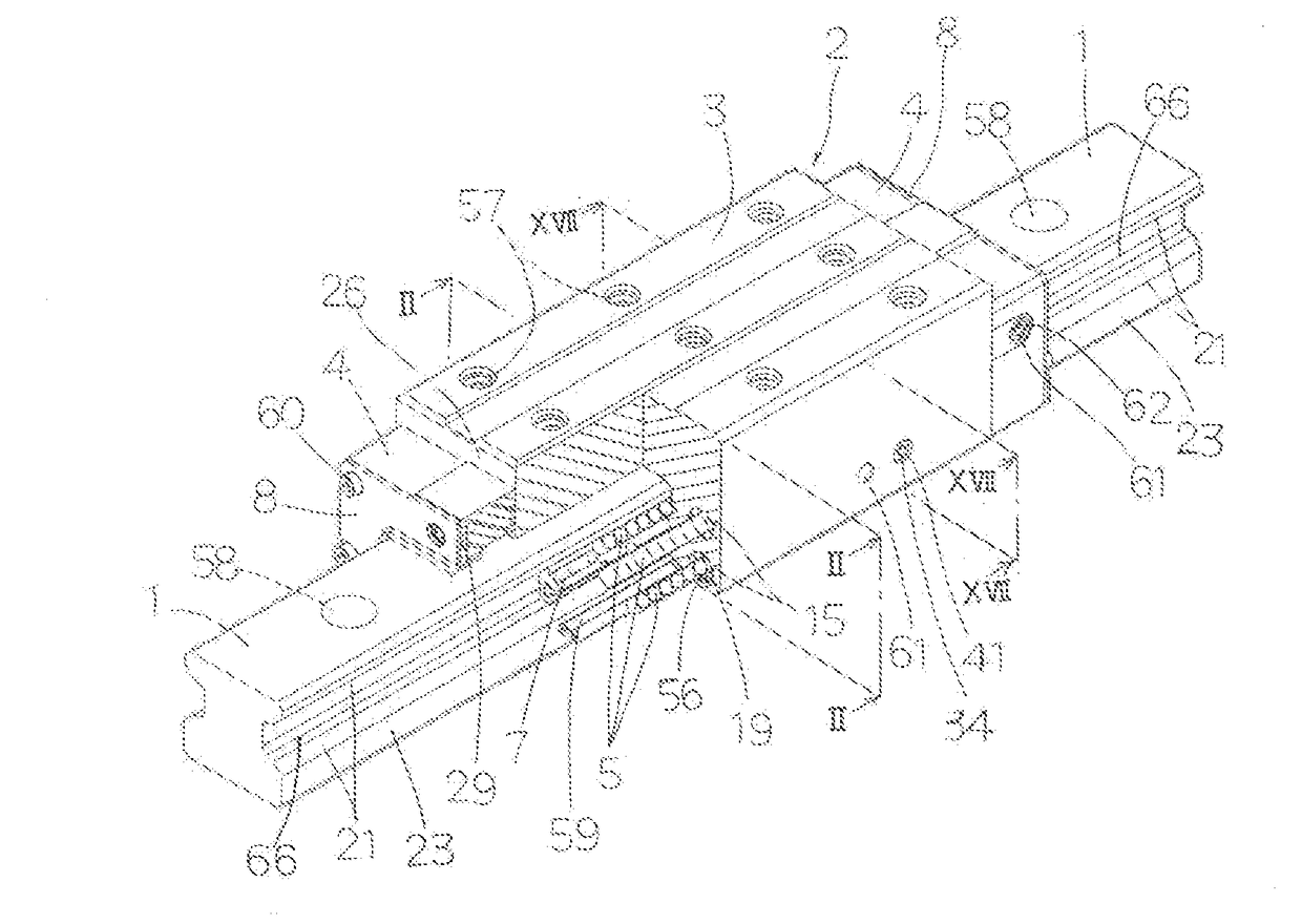
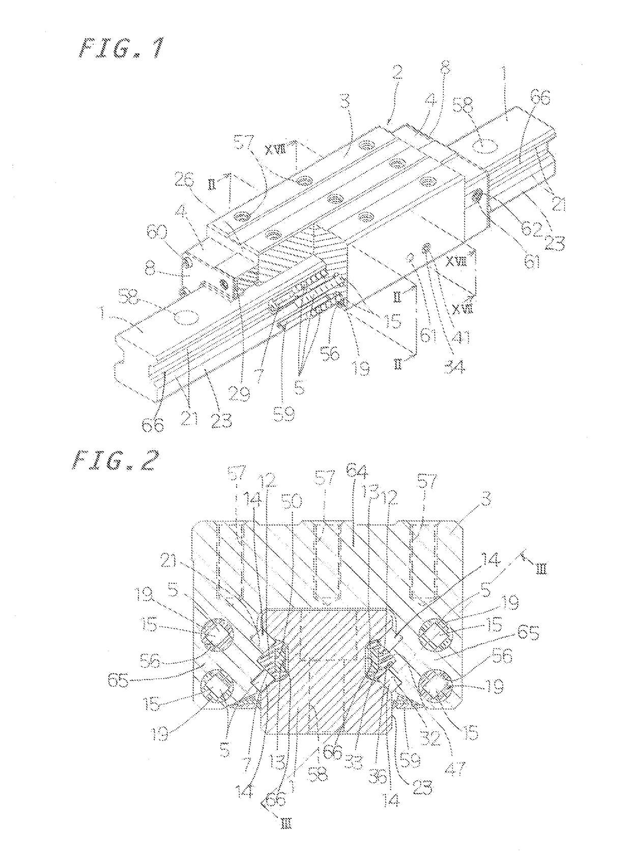
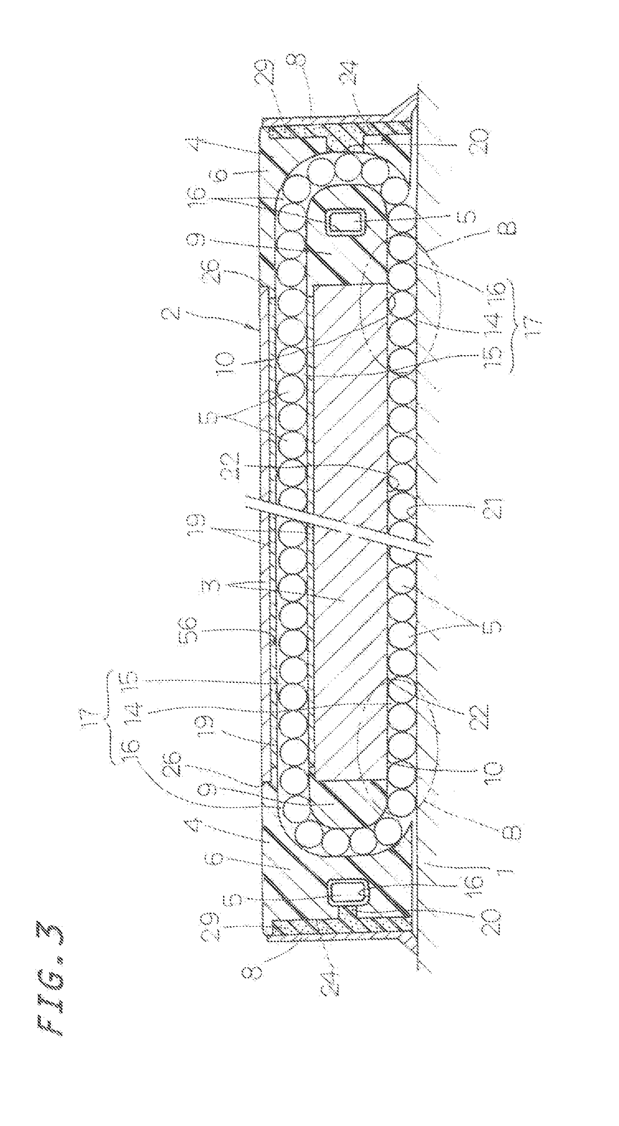
[0037]As shown in FIG. 1, the linear motion guide unit according to the present invention generally includes a guide rail 1 having raceway surfaces 21 (first raceway surfaces) extending in the longitudinal direction on respective longitudinal sides 23 of the guide rail 1, and a slider 2 which has raceway surfaces 22 (second raceway surfaces) facing the respective raceway surfaces 21 as a result of its wing portions straddling the guide rail 1 and which slides in relation to the guide rail 1 via a plurality of rolling elements, or rollers 5, rolling in load-carrying races 14 each composed of the raceway surface...


PUM


Abstract

A linear motion guide unit restrains fluctuations in sliding friction and generation of heat by correcting the postures of rollers having been inclined in a no-load area such that their axes become orthogonal to a guide surface of a carriage to thereby introduce the rollers in proper postures into a load area. A retainer plate of the guide unit has a guide surface for guiding end surfaces of the rollers and has protrusions protruding from the guide surface at its opposite end portions facing crownings of the carriage. The rollers rolling from a turnaround passage to a load-carrying race are pressed by the protrusions toward the guide surface of the carriage so as to be arrayed in such a posture that the axes of the rollers become orthogonal to the guide surface on the inlet side of the crowning of the carriage, whereby the occurrence of roller skew is prevented.

Description

FIELD OF THE INVENTION[0001]The present invention relates to a linear motion guide unit of a roller type in which a retainer plate has means for pressing end surfaces of rollers for arraying the rollers rolling into a load-carrying race such that the axes of the rollers become orthogonal to a guide surface of a carriage.BACKGROUND OF THE INVENTION[0002]According to a conventionally known linear motion guide unit, a retainer plate has a light structure and can be simply and easily held to end caps to thereby reduce the size of a slider. The linear motion guide unit is composed of a guide rail, and the slider moving on the guide rail via rollers. The slider has a carriage and end caps fixed to the respective opposite ends of the carriage. The rollers located on the raceway surface side of the carriage are retained to the carriage by the retainer plate. The retainer plate is fixed to the carriage by screwing fastening bolts inserted through respective insertion holes formed in the carr...

Claims


Application Information

Patent Timeline
Patent Type & Authority Applications(United States)
IPC IPC(8): F16C29/06
CPCF16C29/063F16C29/046F16C29/0607F16C29/0609F16C29/0611F16C29/065F16C29/123
Inventor HAYASHI, TOMOYUKINAGAO, SHOJIMIURA, MASAHIRO
Owner NIPPON THOMPSON
Why Eureka
Try Eureka