Eureka AIR delivers breakthrough ideas for toughest innovation challenges, trusted by R&D personnel around the world.

Optical sensor for detecting accumulation of a material

a technology of optical sensors and accumulations, applied in the field of optical sensors, can solve the problems of increasing drag, reducing lift and drag, and requiring continuous maintenance, and affecting the detection accuracy of material levels

Active Publication Date: 2018-10-04
TYCO ELECTRONICS LOGISTICS AG (CH)
View PDF23 Cites 6 Cited by
  • Summary
  • Abstract
  • Description
  • Claims
  • Application Information

AI Technical Summary

Benefits of technology

The patent describes a sensor that measures reflective light without needing to measure transmitted light outside the sensor. This makes it suitable for harsh, dangerous, or explosive environments. The sensor can be positioned on the surface being monitored without significant modification to the surface. The technical effect is that the sensor provides a more efficient and safe way to measure materials.

Problems solved by technology

Aircraft icing is a dangerous condition.
The formation of ice on the exposed leading edges of wing components changes the aerodynamics of the aircraft and may lead to a decrease in lift and an increase in drag.
These electrical and electro mechanical approaches are subject to significant false readings and require continuous maintenance.
Obviously, any structural modification to a wing component is undesirable as it may compromise the function or structural integrity of the wing component.

Method used


Image

  • Optical sensor for detecting accumulation of a material
  • Optical sensor for detecting accumulation of a material
  • Optical sensor for detecting accumulation of a material

Examples


Embodiment Construction

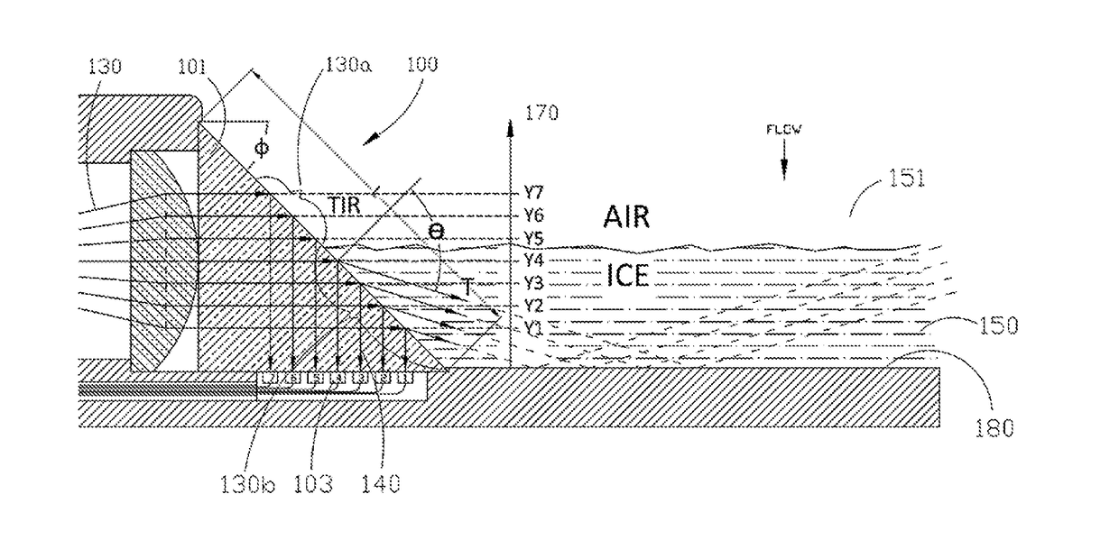
[0024]Referring to FIG. 1, a sensor 100 of the present invention is shown. The sensor 100 is configured for detecting the level of accumulation of a material 150 along an axis 170 in a fluid environment 151. (As used herein, a fluid environment is the environment in which the material accumulates. The fluid(s) of the fluid environment may be gaseous (e.g., air) or liquid (e.g., water), and is (are) displaced by the accumulation of the material.) The material 150 has a first refractive index and the fluid has a second refractive index different from the first refractive index. The sensor comprises an optically transparent body 101 having a third refractive index and at least one exposed surface 101a defining a length l. One of the first or second refractive indexes is lower than the third refractive index. The exposed surface 101a is configured to be exposed to the environment 151 and positioned with the length l extending along the axis 170. The sensor 100 also comprises at least on...


PUM

PropertyMeasurementUnit
angleaaaaaaaaaa
altitudesaaaaaaaaaa
critical angleaaaaaaaaaa

Abstract

A sensor for detecting the level of accumulation of a material along an axis in a fluid environment, the sensor comprising (a) an optically transparent body having a third refractive index and an exposed surface defining a length extending at least partially in the direction of the axis; (b) at least one light delivery source for delivering light to the body such that the light is distributed along the length of the exposed surface; and at least one light receiver for receiving reflected light from the length of the exposed surface, wherein the amount of the reflected light depends on the level of the material accumulated along the length of the exposed surface

Description

FIELD OF INVENTION[0001]The present invention relates, generally, to optical sensors, and, more specifically, to the detection of material levels in a fluid environment such as, for example, the level of icing on an aircraft wing.BACKGROUND[0002]Aircraft icing is a dangerous condition. The formation of ice on the exposed leading edges of wing components changes the aerodynamics of the aircraft and may lead to a decrease in lift and an increase in drag. Typically, the ice formation occurs in clouds at altitudes less than 20,000 ft. (Above this level, the water molecules have already been transformed to ice and will typically just bounce off the foil.) When an aircraft flies through an ice formation zone—i.e., clouds with high moisture content below 20,000 ft. —ice will deposit on the aero-foil. It is critical that excess ice deposits are detected and removed before they cause aerodynamic and mechanical malfunctions and reduce fuel consumption.[0003]Over the years there have been many...

Claims


Application Information

Patent Timeline
Patent Type & Authority Applications(United States)
IPC IPC(8): G01N21/41G01N21/94
CPCG01N21/4133G01N2201/0826G01N2021/945G01N21/94G01N21/552G08B19/02G01F23/292G01B11/06G01F23/00
Inventor GRINDERSLEV, SORENSTOUKLOV, IGORBENTON, MARK
Owner TYCO ELECTRONICS LOGISTICS AG (CH)
Why Eureka
Eureka Blog
Learn More