Spacer Grid Using Tubular Cells With Mixing Vanes

a tubular cell and grid technology, applied in nuclear engineering, nuclear elements, greenhouse gas reduction, etc., can solve the problems of current grid design, limited power within the core, and limited power outpu

Active Publication Date: 2018-10-04
WESTINGHOUSE ELECTRIC CORP
View PDF13 Cites 5 Cited by
  • Summary
  • Abstract
  • Description
  • Claims
  • Application Information

AI Technical Summary

Benefits of technology

[0007]The invention contemplates a nuclear fuel assembly spacer grid having an axial dimension along the vertical axis of an elongated fuel assembly in which it is to be deployed. The nuclear fuel assembly grid comprises a plurality of tubular fuel rod support cells having four walls, generally square in cross section. The walls have a length along the axial dimension that is longer than a width of the walls and substantially flat corners that connect on an interior of the spacer grid with adjacent fuel rod support cells or a control rod support cell, with an interior of each of the walls supporting a vertical spring. The invention also contemplates a mixing vane connected to an exterior of at least one of the fuel rod support cells in an area between fuel rod support cells.

Problems solved by technology

Also, the power within the core is limited by the hottest temperature that can be endured by the fuel assembly components without failure.
The lateral flow of coolant achieves a more uniform radial temperature distribution in the core and allows for a higher power output than could be obtained without the cross-flow of coolant, however, the power output is still limited by the highest temperature experienced by the fuel rods' zirconium cladding.
Since the SiC fuel rods typically have very rough surfaces as shown by reference character 66 in FIG. 3, it is likely that the current grid designs illustrated in FIG. 1, which employ grid spring / dimple features for holding the fuel rods within the fuel assembly, could be damaged during insertion into the fuel skeleton.
The potential for damage is especially a cause for concern for the horizontal dimple design which is typically used in most pressurized water reactor grids.
In the case of the horizontal dimple design, the rough surface of the SiC cladding could hang-up on the dimple and damage the dimple, or it could damage the SiC fuel rod cladding.
Therefore, the current six-point (two springs and four dimples) grid design may not be appropriate for use with SiC fuel cladding.

Method used


Image

  • Spacer Grid Using Tubular Cells With Mixing Vanes
  • Spacer Grid Using Tubular Cells With Mixing Vanes
  • Spacer Grid Using Tubular Cells With Mixing Vanes

Examples


Embodiment Construction

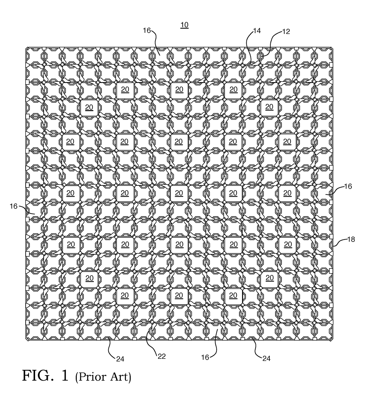
[0020]Many conventional spacer grids are composed of straight grid straps that are interleaved together to form an egg-crate configuration having a plurality of roughly square cells, many of which support fuel rods. An example of such a conventional fuel grid 10 can be found in FIG. 1. A spaced, parallel array of grid straps 12 of equal length are positioned orthogonally to a second plurality of the spaced, parallel grid straps 14 of equal length and are encircled by a border strap 18, with each of the straps being welded at their intersections. The cells 16 support the fuel rods while the cells 20 support guide tubes and an instrumentation tube. Because the fuel rods must maintain a spacing or pitch between each other, these straight grid straps 12 and 14 at the locations that border the cells 16 that support the fuel rods have springs 22 and / or dimples 24 that are stamped in the sides of the straps 12 and 14 to protrude into the cells 16 to contact the fuel rods and hold them firm...


PUM


Abstract

A spacer grid specifically designed for accident tolerant fuel utilizing fuel rods with SiC cladding for implementation in pressurized water reactors. The spacer grid tubular generally square design allows for ease of SiC fuel rod insertion during the fuel assembly fabrication process by providing a smooth contact geometry. The co-planar vertically oriented support allows the fuel rods to be rotated axially more freely at the grid location than a conventional six-point contact geometry used in existing fuel assembly designs. Since the SiC fuel rod has higher stiffness than a metallic fuel rod, the six-point contact geometry, which consists of two spring and four dimples, can potentially damage the fuel rod in the event of fuel rod deflection induced by a seismic event or a bowed fuel assembly. The fuel rod support cells are attached at their corners which are shared between adjacent support cells.

Description

BACKGROUND1. Field[0001]This invention pertains generally to nuclear fuel assemblies and, more specifically, to nuclear fuel assemblies that employ fuel rods with ceramic claddings.2. Related Art[0002]A typical nuclear power reactor includes a reactor vessel housing a nuclear reactor core. Spaced radially, inwardly from the reactor vessel within the interior of the vessel is a generally cylindrical core barrel and within the barrel is a former and a baffle system (hereafter called the “baffle structure”), which permits transition from the cylindrical barrel to a squared-off periphery of the reactor core formed by the fuel assemblies arrayed therein.[0003]The reactor core is composed of a large number of elongated fuel assemblies. Each fuel assembly includes a plurality of fuel rods containing the fissile material, which reacts to produce heat. The fuel rods of each fuel assembly are held in an organized, spaced array by a plurality of grids, spaced axially along the fuel assembly le...

Claims


Application Information

Patent Timeline
Patent Type & Authority Applications(United States)
IPC IPC(8): G21C3/344G21C3/356
CPCG21C3/344G21Y2004/303G21C2003/3432G21C3/356G21C3/3563Y02E30/30G21C3/322G21C3/34
Inventor CHOI, JOONHYUNGKAROUTAS, ZESESEVANS, PAUL M.
Owner WESTINGHOUSE ELECTRIC CORP
Why Eureka
Try Eureka