Wireless communication system that performs measurement based selection of phase tracking reference signal (PTRS) ports

a phase tracking reference signal and wireless communication technology, applied in the field of mobile telecommunications, can solve the problems of high overhead, leakage degrade the orthogonality of the waveform, and inefficiency with respect to the use of available bandwidth

Active Publication Date: 2018-10-04
NATIONAL INSTRUMENTS
View PDF0 Cites 37 Cited by
  • Summary
  • Abstract
  • Description
  • Claims
  • Application Information

AI Technical Summary

Problems solved by technology

Phase noise introduces two kinds of impairment on OFDM-based systems: (1) common phase error (CPE) and (2) inter-carrier interference (ICI).
The phase noise at each subcarrier frequency also introduces ICI to the neighboring subcarriers, and this spectral leakage degrades the orthogonality of the OFDM waveform.
This CPE estimation based on a static pilot pattern, therefore, has the drawback of high overhead due to required pilot signaling for the purely pilot aided PN compensation.
While the use of PTRS ports and related communications can help improve CPE compensation, they can also lead to inefficiencies with respect to the use of available bandwidth and difficulties arise in the selection and allocation of the PTRS ports by the base station(s).

Method used


Image

  • Wireless communication system that performs measurement based selection of phase tracking reference signal (PTRS) ports
  • Wireless communication system that performs measurement based selection of phase tracking reference signal (PTRS) ports
  • Wireless communication system that performs measurement based selection of phase tracking reference signal (PTRS) ports

Examples


example communication

Environments for the Disclosed Embodiments

[0049]With respect to the descriptions provided herein, the following abbreviations are used:[0050]PTRS: Phase Tracking Reference Signal[0051]DMRS: Demodulation Reference Signal[0052]TRP: Transmission Reception Point[0053]gNB: g NodeB (base station)[0054]PSD: Power Spectral Density[0055]PN: Phase Noise[0056]TTI: Transmission Time Interval, the minimum scheduling interval for a UE

Example Architectures of Base Station (BS) and User Equipment (UE)

[0057]The following are example architectures that can be used for base station (BS) and user equipment (UE) implementations within a wireless communication system. As these are example embodiments, it is understood that additional and / or different architectures could be used.

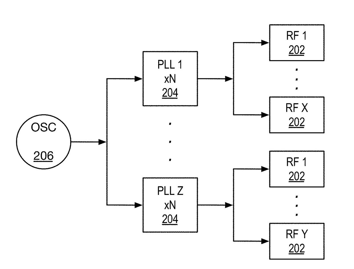
[0058]At the TRP the following are example architectures:[0059]One antenna panel only[0060]One LO (local oscillator) shared between all antennas of the panel[0061]Multiple LOs shared between the antennas of the panel[0062]With com...

example

[0158]Continuing the example from the feedback Type 1 above, the UE measures the 6×6 cross correlation matrix, and in this instance finds that the phase noise process on spatial streams 1 and 2 are highly correlated, and that those on spatial streams 3, 4, 5, 6 are highly uncorrelated. In that case, it may request the TRP to allocate five spatial streams and to map PTRS port 1 to DMRS port 1, to map no PTRS ports to DMRS port 2, and to map PTRS ports 2 through 5 to DMRS ports 3 through 6, respectively. It is noted that DMRS port 5 and 6 are used for another UE for this example.

Example Flow Diagrams

[0159]FIGS. 6A-C provide an example flow diagram for performing the PN correlation at the UEs and for the feedback of these correlations from the UE to the base station. It is noted that although the discussions herein focus on the DL, these methods can be extended to UL in a similar manner.

[0160]Looking first to FIG. 6A, at block 602, when PTRS communications are supported by the base sta...


PUM


Abstract

A base station (BS) having a plurality of antennas transmits a plurality of spatial streams. Each user equipment (UE) of a plurality of UE estimates common phase error (CPE) of each of two or more of the plurality of spatial streams, measures correlations of the estimated CPE among the two or more of the plurality of spatial streams, and provides feedback about the CPE correlations to the BS. The BS uses the CPE correlation feedback to allocate phase tracking reference signal (PTRS) ports and to map the allocated PTRS ports to demodulation reference signal (DMRS) ports corresponding to the plurality of spatial streams.

Description

[0001]This application claims priority based on U.S. Provisional Application Ser. No. 62 / 480,806, filed Apr. 3, 2017, entitled MEASUREMENT BASED SELECTION OF PHASE TRACKING REFERENCE SIGNAL (PT-RS) PORTS FOR WIRELESS COMMUNICATION SYSTEMS, which is hereby incorporated by reference in its entirety.TECHNICAL FIELD[0002]The disclosed embodiments relate to mobile telecommunications.BACKGROUND[0003]The New Radio (NR) definition in 3GPP (3rd Generation Partnership Project) for mobile systems will encompass a variety of deployment scenarios envisioned for 5G (fifth generation) mobile communication systems. MIMO (multiple input, multiple output) communication systems can be used for 5G TDD (time division duplex) air interfaces. Flexible (scalable) frame structures are being considered for block symbol transmissions within the new 5G cellular communication standard including various frame structure parameters such as FFT (fast Fourier transform) size, sample rate, and subframe length.[0004]F...

Claims


Application Information

Patent Timeline
Patent Type & Authority Applications(United States)
IPC IPC(8): H04L5/00H04L27/26
CPCH04L5/0048H04L27/2602H04L5/0023H04L5/0051H04L27/2613H04W56/0035H04B7/0417H04B7/0626H04L27/26136H04L27/26134
Inventor KUNDARGI, NIKHIL U.NAHLER, ACHIM
Owner NATIONAL INSTRUMENTS
Why Eureka
Try Eureka