Supercharge Your Innovation With Domain-Expert AI Agents!

Pillar display system for blind spot of vehicle

a technology for blind spots and display systems, which is applied in the direction of cameras, instruments, transportation and packaging, etc., can solve the problems of affecting the front and side visual fields of drivers, blind spots are caused at the front and side areas, and blind spot mirrors deteriorating the esthetic appearance of vehicles, so as to achieve the effect of minimizing distortion

Active Publication Date: 2018-10-11
HYUNDAI MOTOR CO LTD +1
View PDF2 Cites 26 Cited by
  • Summary
  • Abstract
  • Description
  • Claims
  • Application Information

AI Technical Summary

Benefits of technology

The present invention aims to solve the problems of conventional art by showing an image on a pillar corresponding to a blind spot on the basis of the viewing angle of the driver. The invention provides a blind spot image continuously displayed on both the windshield glass and side glass, minimizing deterioration of the driver's field of view. Additionally, the invention allows the driver to easily recognize the blind spot of a vehicle while driving. Furthermore, the invention provides a clear image throughout the entire pattern area rather than display the blind spot on a portion of the pillar. Overall, the invention improves driving safety and provides better visibility for the driver.

Problems solved by technology

However, pillars of a vehicle may interfere with front and side front visual fields of a driver when he or she drives the vehicle.
That is, blind spots are caused at the front and side areas of a vehicle due to the pillars.
As a device for removing blind spots due to the pillars, blind spot mirrors are mounted or attached to a vehicle, but the blind spot mirrors deteriorate the esthetic appearance of vehicles.
Furthermore, since the blind spot mirrors are convex mirrors, they deteriorate depth perception of a driver, so the blind spot mirrors cause a side effect instead, which is not preferable in terms of safety.
Furthermore, there is a system that can remove blind spots by taking motion pictures of the front area or the side front areas of a vehicle using cameras on the external sides of pillars and displaying the images through a monitor, but the directions of the images are distorted depending on the eye direction (viewing angle) of the driver, so he or she cannot exactly recognize the external situations.
Furthermore, when the vehicle approaches an obstacle, the driver does not have enough time to recognize and cope with the obstacle, so it is difficult for the driver to prevent a collision.

Method used


Image

  • Pillar display system for blind spot of vehicle
  • Pillar display system for blind spot of vehicle
  • Pillar display system for blind spot of vehicle

Examples


Embodiment Construction

[0040]Reference will now be made in detail to various embodiments of the present invention(s), examples of which are illustrated in the accompanying drawings and described below. While the invention(s) will be described in conjunction with exemplary embodiments, it will be understood that the present description is not intended to limit the invention(s) to those exemplary embodiments. On the contrary, the invention(s) is / are intended to cover not only the exemplary embodiments, but also various alternatives, modifications, equivalents and other embodiments, which may be included within the spirit and scope of the invention as defined by the appended claims.

[0041]Furthermore, in the specification, the terms “˜unit” mean one device for processing at least one function or operation and may be achieved by a combination of hardware.

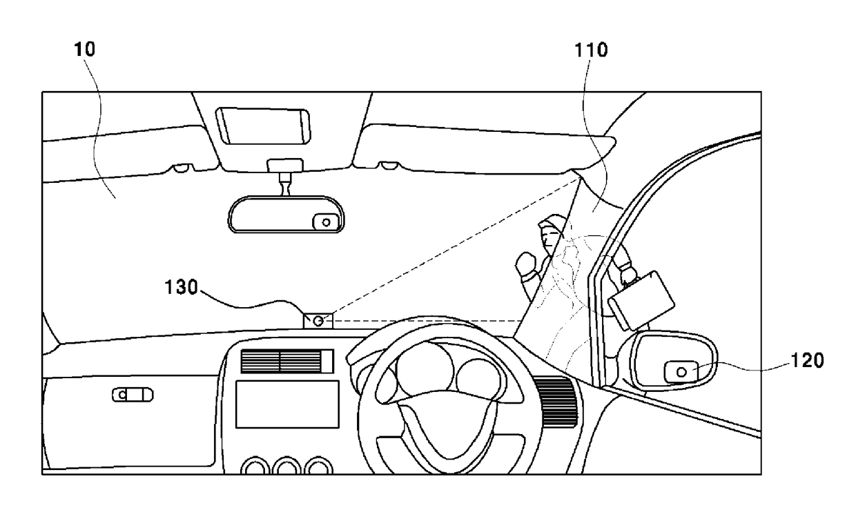
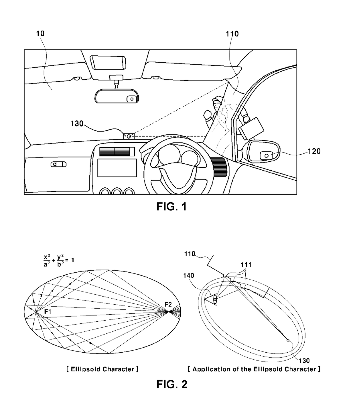
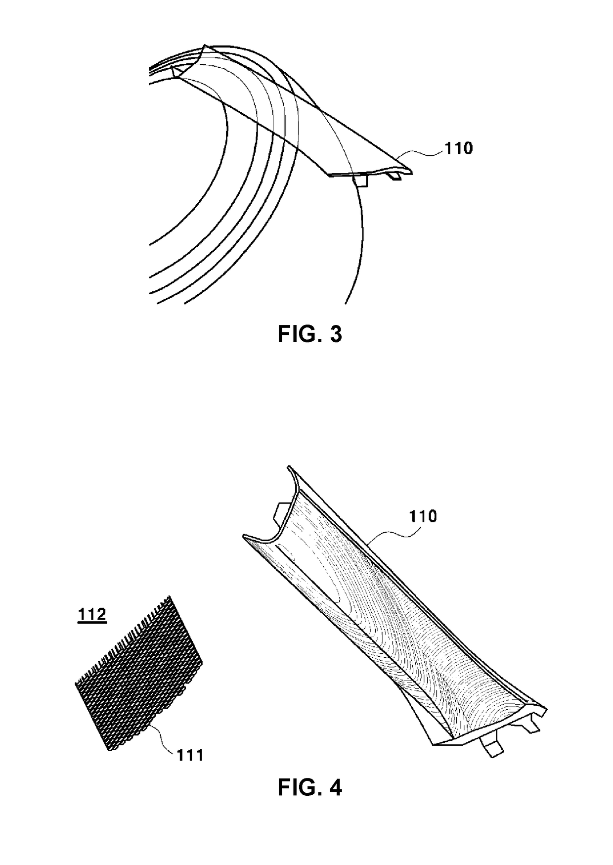
[0042]Various aspects of the present invention are directed to providing a pillar display system for a blind spot of a vehicle that can display the blind spot...


PUM


Abstract

A pillar display system for a blind spot of a vehicle may include an A-pillar disposed inside a vehicle; and an image projector projecting a blind spot image of the vehicle taken with a camera, wherein a plurality of virtual ellipsoids are formed by setting an area where a driver's eyes are positioned and the image projector as focuses, and a pattern area formed by a combination of facets of the virtual ellipsoids is disposed at a position where the virtual ellipsoids and the A-pillar meet each other wherein the image from the image projector is displayed on the pattern area.

Description

CROSS-REFERENCE(S) TO RELATED APPLICATIONS[0001]The present application claims priority to Korean Patent Application No. 10-2017-0046056, filed on Apr. 10, 2017, the entire contents of which are incorporated herein for all purposes by this reference.BACKGROUND OF THE INVENTIONField of the Invention[0002]The present invention relates to a pillar display system for a blind spot of a vehicle. More particularly, the present invention relates to a pillar display system for a blind spot of a vehicle, the system improving a driving environment for a driver by displaying an image of a blind spot on a pillar, on which a pattern area is formed.Description of Related Art[0003]In general, a vehicle body that forms the external shape of a vehicle includes a floor panel forming the bottom portion of the vehicle, a frame for maintaining a strength of the vehicle body, pillars disposed at sides of the vehicle body, a roof panel forming a top portion of the vehicle body, and doors.[0004]A driver see...

Claims


Application Information

Patent Timeline
IPC IPC(8): B60R1/00G03B21/00B60R11/04
CPCB60R1/002G03B21/00B60R11/04B60R2300/202B60R2300/802B60R2300/602B60R2300/205B60R1/25G03B17/54G03B21/28G03B21/60B60R1/081B62D25/04B60R2300/105
Inventor CHO, YONG JOO
Owner HYUNDAI MOTOR CO LTD
Features
  • R&D
  • Intellectual Property
  • Life Sciences
  • Materials
  • Tech Scout
  • Unparalleled Data Quality
  • Higher Quality Content
  • 60% Fewer Hallucinations
Learn More