Electric tinfoil-cutting device for automatic corkscrews

a cutting device and automatic technology, applied in the field of wine corkscrews, can solve the problems inconvenient use of corkscrews, and many defects in the above-mentioned corkscrew, and achieve the effect of high automation degree, convenience of use, and new structural design

Active Publication Date: 2018-10-11
ZHUHAI KELITONG ELECTRONICS CO LTD
View PDF0 Cites 1 Cited by
  • Summary
  • Abstract
  • Description
  • Claims
  • Application Information

AI Technical Summary

Benefits of technology

[0005]In view of the defects in the prior art, the present utility model aims to provide an electric tinfoil-cutting device for automatic corkscrews which has the advantages of novel structural design, high automation degree and convenience in use, and can achieve an automatic tinfoil-cutting function.
[0012]The present utility model has the following advantages that the electric tinfoil-cutting device for automatic corkscrews disclosed by the present utility model comprises the reduction gearbox, the driving motor mounted at the lower end of the reduction gearbox, and the movable support mounted at the upper end of the reduction gearbox, the power output end of the reduction gearbox is connected to the movable support, the blade assembly is embedded in the support receiving cavity in the movable support, the blade assembly comprises the blade-mounting carrier which is provided with the mounting carrier limit notches at its edge, the internal wall of the support receiving cavity is provided with the support limit projections, each support limit projection is provided with the guide slope, and the support limit projections are embedded in the mounting carrier limit notches; the blade-mounting carrier is provided with the blade-mounting holes, the L-shaped blade-mounting blocks are embedded in the blade-mounting holes, each blade-mounting block comprises the horizontal mounting block portion and the vertical mounting block portion, the horizontal mounting block portions are embedded in the blade-mounting holes and pushed outwardly by the horizontal springs, and the tinfoil-cutting blades are mounted at the upper ends of the vertical mounting block portions. By means of the above-mentioned structural design, the present utility model can achieve the automatic tinfoil-cutting function, that is, the electric tinfoil-cutting device of the present utility model has the advantages of novel structural design, high automation degree and convenience in use.

Problems solved by technology

However, in actual use, the above-mentioned corkscrew has a lot of defects.
As a result, the winebottle opening process is time-consuming and laborious, and the corkscrew is very inconvenient to use.
However, for a conventional automatic corkscrew, in the process of opening a winebottle, it tends to use a tinfoil cutter to cut the tinfoil on the bottleneck; moreover, conventional tinfoil cutters are all operated manually, so that the process is time-consuming and laborious.

Method used


Image

  • Electric tinfoil-cutting device for automatic corkscrews
  • Electric tinfoil-cutting device for automatic corkscrews
  • Electric tinfoil-cutting device for automatic corkscrews

Examples


Embodiment Construction

[0027]The present utility model is described below with reference to specific embodiments.

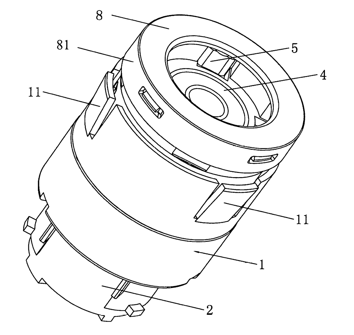
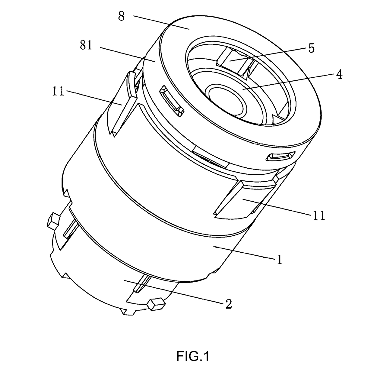
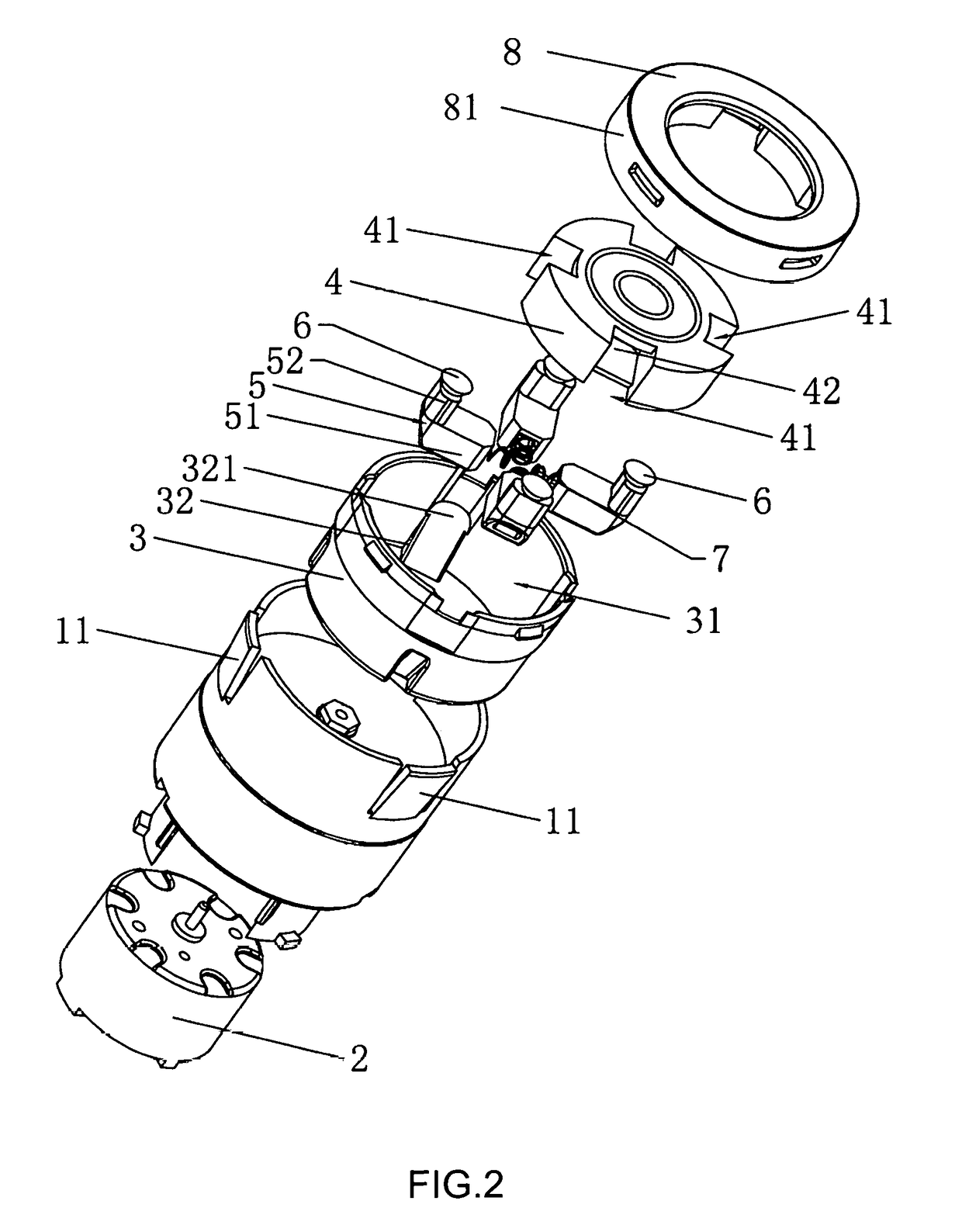
[0028]As shown in FIG. 1 to FIG. 3, disclosed is an electric tinfoil-cutting device for automatic corkscrews, which comprises a reduction gearbox 1 and a driving motor 2 mounted at a lower end of the reduction gearbox 1, a power output shaft of the driving motor 2 is connected to a power input end of the reduction gearbox 1, a movable support 3 is mounted at un upper end of the reduction gearbox 1, a power output end of the reduction gearbox 1 is connected to the movable support 3, and a support receiving cavity 31 with an upward opening is formed in the movable support 3.

[0029]Further, a blade assembly is embedded in the support receiving cavity 31 of the movable support 3, the blade assembly comprises a blade-mounting carrier 4 which is embedded in the support receiving cavity 31, the edge of the blade-mounting carrier 4 is provided with at least two mounting carrier limit notches 41 which bo...


PUM


Abstract

The present utility model discloses an electric tinfoil-cutting device for automatic corkscrews, which comprises a reduction gearbox, a driving motor, a movable support and a blade assembly comprising a blade-mounting carrier and blade-mounting blocks, wherein the movable support are provided with support limit projections which are embedded in mounting carrier limit notches of the blade-mounting carrier, each of the blade-mounting blocks comprises a horizontal mounting block portion and a vertical mounting block portion, and a tinfoil-cutting blade is mounted on the vertical mounting block portion. The electric tinfoil-cutting device of the present utility model can achieve an automatic tinfoil-cutting function and has the advantages of novel structural design, high degree of automation, and convenience in use.

Description

BACKGROUND OF THE INVENTION[0001]The present utility model relates to the technical field of wine corkscrews, and in particular to an electric tinfoil-cutting device for automatic corkscrews.[0002]A wine corkscrew is an auxiliary tool for pulling a winebottle cork out of the bottleneck of a winebottle. A common corkscrew normally comprises a main body for convenient holding by an operator and a screw connected to the main body. When held by hand and rotated, the main body drives the screw to screw into a cork, and then brings the cork out of a winebottle, thereby completing the winebottle opening. However, in actual use, the above-mentioned corkscrew has a lot of defects. For example, in order to open the winebottle, the winebottle must be positioned directly below the screw, and the screw must be located on the axis of the cork as much as possible. The winebottle is then held by the left hand with the right hand rotating and driving the screw into the cork, and the cock cannot be p...

Claims


Application Information

Patent Timeline
Patent Type & Authority Applications(United States)
IPC IPC(8): B67B7/04
CPCB67B7/0405B67B2007/0458B67B7/38
Inventor SONG, XIAOXIANZHU, HAIHONG
Owner ZHUHAI KELITONG ELECTRONICS CO LTD
Why Eureka
Try Eureka