Inflating stick and processing machine

a technology which is applied in the field of inflating stick and processing machine, to achieve the effect of facilitating gas flow

Active Publication Date: 2018-10-18
AIR BAG PACKING +1
View PDF6 Cites 3 Cited by
  • Summary
  • Abstract
  • Description
  • Claims
  • Application Information

AI Technical Summary

Benefits of technology

[0015]According to the design of the structure of the inflating stick, the cone structure of the front end of the inflating stick is easily inserted into the inflating channel of the gas sealed body to inflate. The rear end of the inflating stick having a larger size corresponds to films with wrinkles, which facilitates gas flow from the gas outlets to the gas columns Further, the wrinkles can become smooth so that the cutter can successfully cut the side end of the gas sealed body; therefore, the link rod won't block the side end of the gas sealed body. The gas columns being inflated can be successfully retrieved and reeled in. In addition, the pressing wheels of the processing machine drive the gas sealed body to move forward and press the side end of the gas sealed body. The issue that the gas column may shift due to contraction caused by inflation when the gas sealed body is inflated, can be improved.

Problems solved by technology

If situations causing the package bags to have wrinkles or be packed together are not solved, the process may not work well and may cause danger.

Method used


Image

  • Inflating stick and processing machine
  • Inflating stick and processing machine
  • Inflating stick and processing machine

Examples


first embodiment

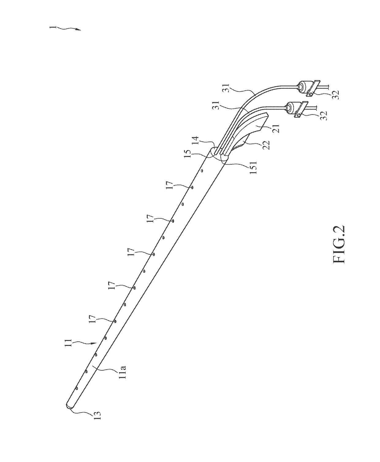
[0037]Please refer to FIG. 2. FIG. 2 is a perspective view of an inflating stick 1 according to the In the embodiment, the inflating stick 1 is, but is not limited to, a long stick structure. In some aspects, the inflating stick 1 is made by a plurality of spheres 11b connected in series (as shown in FIG. 4). In the embodiment, the inflating stick 1 comprises a body 11, a link rod 21, a cutter 22, and a plurality of inflating tubes 31. Alternatively, only one inflating tube 31 in the inflating stick 1 is acceptable.

[0038]Please refer to FIG. 2 and FIG. 3. FIG. 3 is a side view of the inflating stick 1 according to the first embodiment. The body 11 is a long cone 11a. Inside of the body 11 is hollow. The body 11 is made by metal or plastic. The size of the body 11 gradually increases from a front end to a rear end to form a guiding segment 13 and a packing segment 14. A head of the guiding segment 13 is easily inserted into an inflating channel 90 of a gas sealed body 9 due to small...

third embodiment

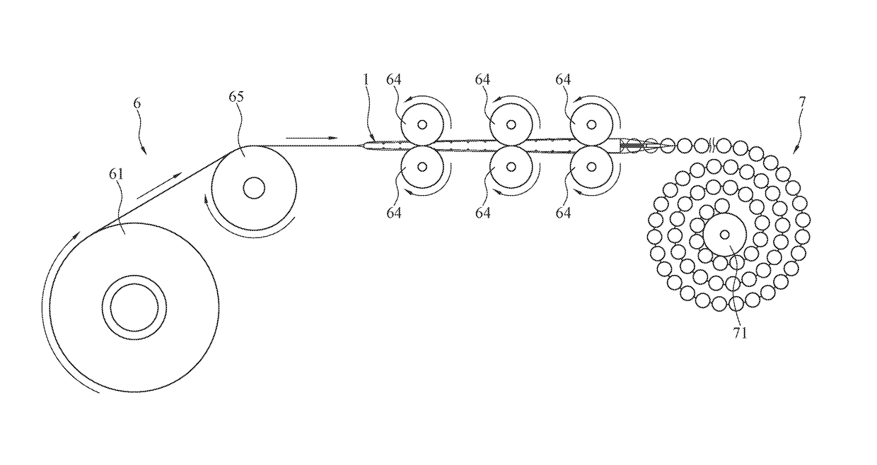
[0039]The whole inflating stick 1 having a cone structure is the first aspect. Some other aspects of the inflating stick 1 can be referred to FIG. 13 and FIG. 14. FIG. 13 is a perspective view of a processing machine according to the FIG. 14 is a perspective view of an inflating stick 1 according to another aspect. In the embodiment, the inflating stick 1 is the second aspect. The guiding segment 13 of the body 11 of the inflating stick 1 is designed to form the cone structure. The guiding segment 13 with the cone structure extends outside of two pressing wheels 64, which are an upper pressing wheel 64 and a lower pressing wheel 64, to be easily inserted into an inflating channel 90 of a gas sealed body 9. The guiding segment 13 of the inflating stick 1 is a cone structure (a cone); however, a middle part of the body 11 to the rear end of the body 11 is a tube, which is a tube structure having an identical diameter. In other words, the whole inflating stick 1 is a cone at the front...

second embodiment

[0044]Please refer to FIGS. 4, 11, and 12. FIG. 12 is a top view of the processing machine according to the In the embodiment, a cross section of the sphere 11b can form a substantially concave-convex shape, and a cross section corresponding to the gas columns 95 of the gas sealed body 9 can form a substantially concave-convex shape. The outer wall of the spheres 11b has a plurality of gas outlets 17. After the spheres 11b are inserted into the inflating channel 90 of the gas sealed body 9 and inflating, the inflated gas columns 95 are expanded. A cross section of each of the inflated gas columns 95 is a substantially sphere shape. A cross section of each of the gas columns 95 not inflated remains a flat shape Films 91 of the gas columns 95 not inflated are easily wrinkled by each other because the films 91 are not spread. In other words, the contraction of each of the films 91 leads to the formation of a wrinkle area 94 (as shown in FIG. 6). The gas columns 95 not inflated are pac...


PUM


Abstract

An inflating stick and a processing machine are provided. The inflating stick includes a body, a link rod, a cutter, and one or more inflating tubes. A front end of the body includes a guiding segment with a cone structure. A rear end of the body includes a packing segment. The body includes a gas inlet formed on the packing segment, an internal chamber allowing gas to flow into through the gas inlet, and gas outlets formed on an outer wall of the body allowing gas to flow out. The packing segment includes a first locking structure and a second locking structure. The first locking structure and the second locking structure communicate with the gas inlet. The second locking structure is detachably fastened to the first locking structure. The link rod and the cutter are disposed in rear of the body. The inflating tube is connected to the gas inlet.

Description

CROSS-REFERENCE TO RELATED APPLICATION[0001]This application is a continuation-in-part (CIP) of application Ser. No. 15 / 354,582, filed on Nov. 17, 2016 with claiming foreign priority of TW104138357. The prior application is herewith incorporated by reference in its entirety.BACKGROUNDTechnical Field[0002]The instant disclosure relates to an inflating structure of a gas sealed body and, more particularly, to an inflating stick and a processing machine.Related Art[0003]At present, equipment for manufacturing inflated package bags includes a front end for placing work pieces, a processing platform, and a rear retrieving rack. The processing platform receives package bags not inflated from the front end. An inflating device on the processing platform inflates the package bags. The inflated package bags are continuously transported to the rear retrieving rack to be retrieved and reeled in.[0004]Please refer to FIG. 1. FIG. 1 is a top view of continuous sealed bags. U.S. Pat. No. 5,261,46...

Claims


Application Information

Patent Timeline
Patent Type & Authority Applications(United States)
IPC IPC(8): B65B43/12B65D81/03
CPCB65B43/123B65D81/03B65D81/052B65D31/142B31D5/0073B31D5/0039B31D2205/0023B31D2205/0052B31B2100/00B31B70/20
Inventor LIAO, TAI-ANLIAO, KAO-HSIUNGLIAO, CHIEH-HUA
Owner AIR BAG PACKING
Why Eureka
Try Eureka