
Connection Structure of Exhaust Bearing Seat for Compressor and Screw Compressor

a screw compressor and bearing seat technology, which is applied in the direction of machines/engines, rotary/oscillating piston pump components, liquid fuel engines, etc., can solve the problems of reducing affecting the stability of the rotor, and affecting the service life of the bearing seat, so as to reduce the radial vibration of the tail portion, avoid the problem of rotor scratching, and improve the rotor rotation stably

Active Publication Date: 2018-10-18
GREE ELECTRIC APPLIANCES INC
View PDF7 Cites 0 Cited by
  • Summary
  • Abstract
  • Description
  • Claims
  • Application Information

AI Technical Summary

Benefits of technology

The present disclosure provides a connection structure for an exhaust bearing seat that reduces radial vibration, which can cause problems such as scratches and abnormal noise. This structure includes a vibration-reducing element between the exhaust bearing seat and the oil separation screen assembly, which suppresses vibration and improves the rotor's stability. This results in a screw compressor that has less radial vibration, longer service life, and wider application scope.

Problems solved by technology

However, during operation of the screw compressor, the intermittent opening / closing of the exhaust port generates a complex gas pulsation, and the gas pulsation acts on the bearing seat to cause high frequency vibration of the latter, which is disadvantageous to stable operation of the rotor.
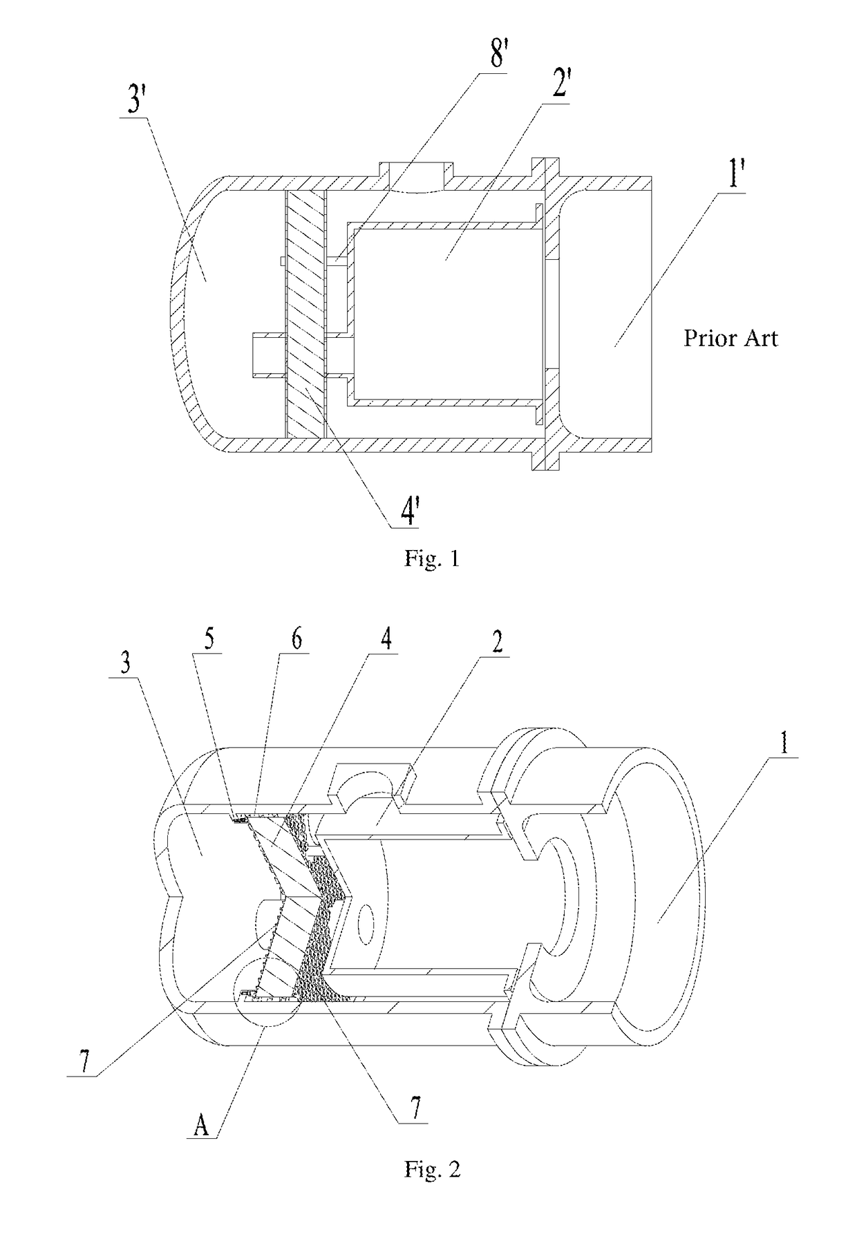
The oil separation screen 4′ becomes very heavy due to high content of lubricating oil, and suspension of the heavy oil separation screen 4′ on the tail portion of the bearing seat 2′ cause greater vibration of the bearing seat 2′.
Such connection structure of the bearing seat causes a variety of hazards, such as reduced service life of the bearing due to misalignment, scratch of the rotor and slide valves, abnormal noise of the screw compressor, and even machine run-down and motor burnout, etc.

Method used


Image

  • Connection Structure of Exhaust Bearing Seat for Compressor and Screw Compressor
  • Connection Structure of Exhaust Bearing Seat for Compressor and Screw Compressor
  • Connection Structure of Exhaust Bearing Seat for Compressor and Screw Compressor

Examples


Embodiment Construction

[0032]The technical solution of the present disclosure will be further described as below in combination with the drawings through the specific embodiments.

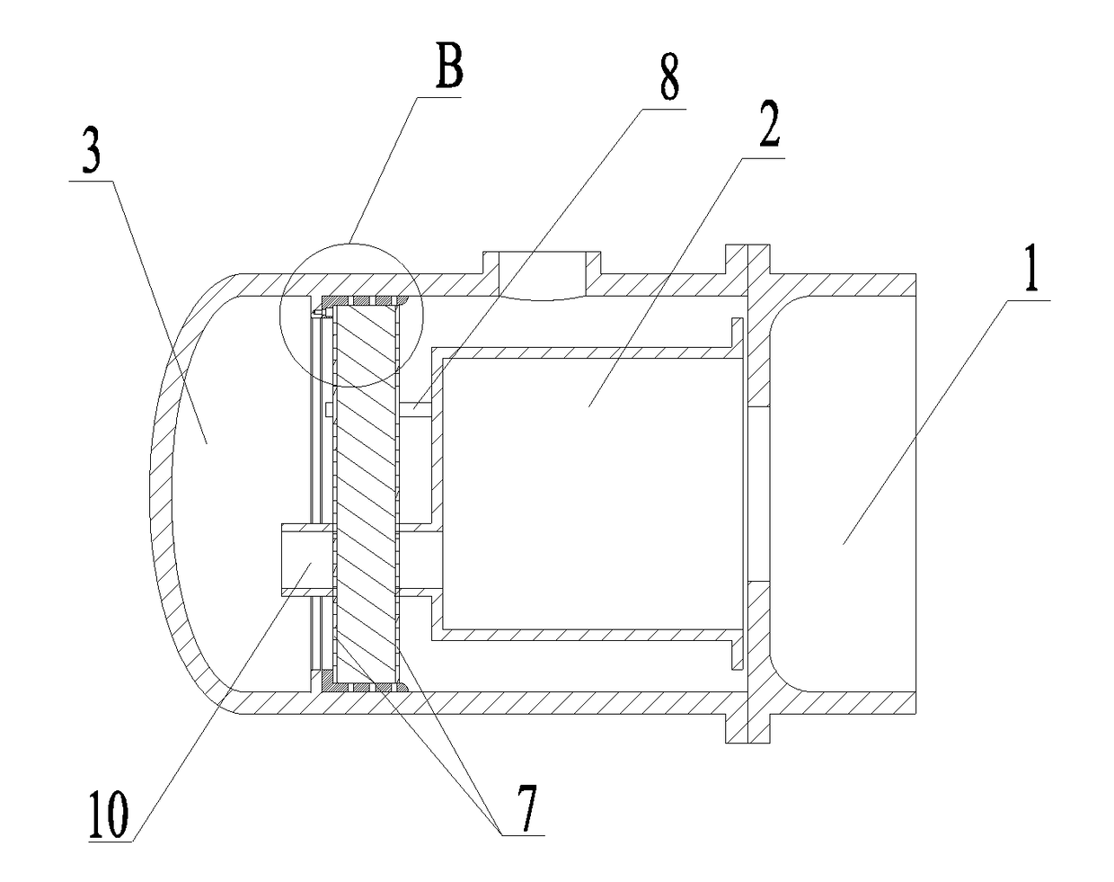
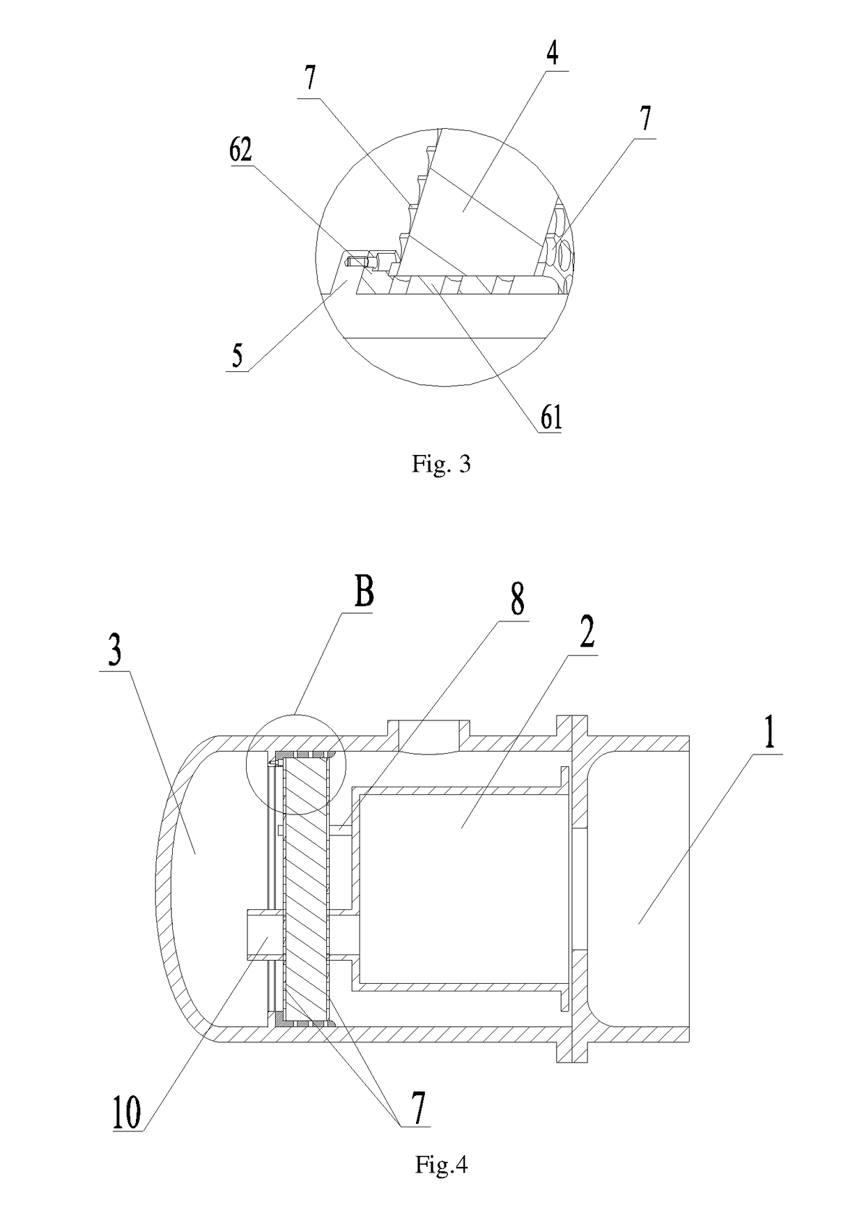
[0033]The present embodiment provides a connection structure of an exhaust bearing seat for a compressor, which as shown in FIGS. 2-5, comprises an exhaust bearing seat 2, an oil separation bucket 3, and an oil separation screen assembly 4 all arranged at an exhaust end of a body 1 of the compressor. Referring to FIG. 2, a tail end of the exhaust bearing seat 2 is connected with the oil separation screen assembly 4, and an outer periphery of the oil separation screen assembly 4 is provided with a vibration-reducing element 6, which is connected with an inner wall of the oil separation bucket 3.

[0034]The exhaust bearing seat 2, the oil separation bucket 3, and the oil separation screen assembly 4 are all arranged at the exhaust end of the body 1 of the compressor. Specifically, the exhaust bearing seat 2 is disposed at the exhaust...


PUM


Abstract

Disclosed is a connection structure of an exhaust bearing seat for compressors and screw compressors, designed to solve the problem of large radial vibration of the existing exhaust-end bearing seat. The connection structure includes an exhaust bearing seat, an oil separation bucket, and an oil separation screen assembly all arranged at an exhaust end of a body of the compressor, wherein a tail end of the exhaust bearing seat is connected with the oil separation screen assembly, and an outer periphery of the oil separation screen assembly is provided with a vibration-reducing element, which is connected to an inner wall of the oil separation bucket. The vibration of the exhaust bearing seat is transmitted to the vibration-reducing element through the oil separation screen assembly, and then to the oil separation bucket after being absorbed and suppressed by the vibration-reducing element.

Description

FIELD OF THE INVENTION[0001]The present disclosure relates to the field of compressors, and in particular to a connection structure of an exhaust bearing seat for a compressor and a screw compressor.DESCRIPTION OF RELATED ART[0002]An exhaust-end bearing seat, as an important casting of a screw compressor, not only functions to support a rotor, but also acts as an exhaust channel of the compressed gas.[0003]However, during operation of the screw compressor, the intermittent opening / closing of the exhaust port generates a complex gas pulsation, and the gas pulsation acts on the bearing seat to cause high frequency vibration of the latter, which is disadvantageous to stable operation of the rotor. As shown in FIG. 1, a tail portion of an exhaust-end bearing seat 2′ connected with a body 1′ of the screw compressor is connected to an oil separation screen 4′ through a spacer pipe 8′, such that vibration of the bearing seat 2′ causes the oil separation screen 4′ to vibrate. The oil separa...

Claims


Application Information

Patent Timeline
Patent Type & Authority Applications(United States)
IPC IPC(8): F04C29/12F04C15/06
CPCF04C29/12F04C15/06F04C29/026F04C18/16F04C2270/12
Inventor MA, BINZHANG, TIANYILI, RIHUALIU, HUABI, YUSHIYANG, QIAOMINGPENG, YANHAIXU, KANGMENG, QIANGJUNXU, YUNGONG
Owner GREE ELECTRIC APPLIANCES INC
Learn More