Eureka AIR delivers breakthrough ideas for toughest innovation challenges, trusted by R&D personnel around the world.

Turbine engine and containment assembly for use in a turbine engine

Active Publication Date: 2018-10-18
GENERAL ELECTRIC CO
View PDF37 Cites 3 Cited by
  • Summary
  • Abstract
  • Description
  • Claims
  • Application Information

AI Technical Summary

Benefits of technology

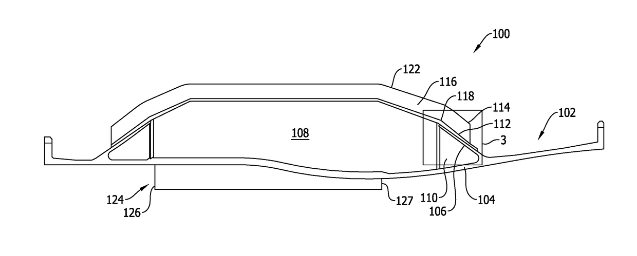
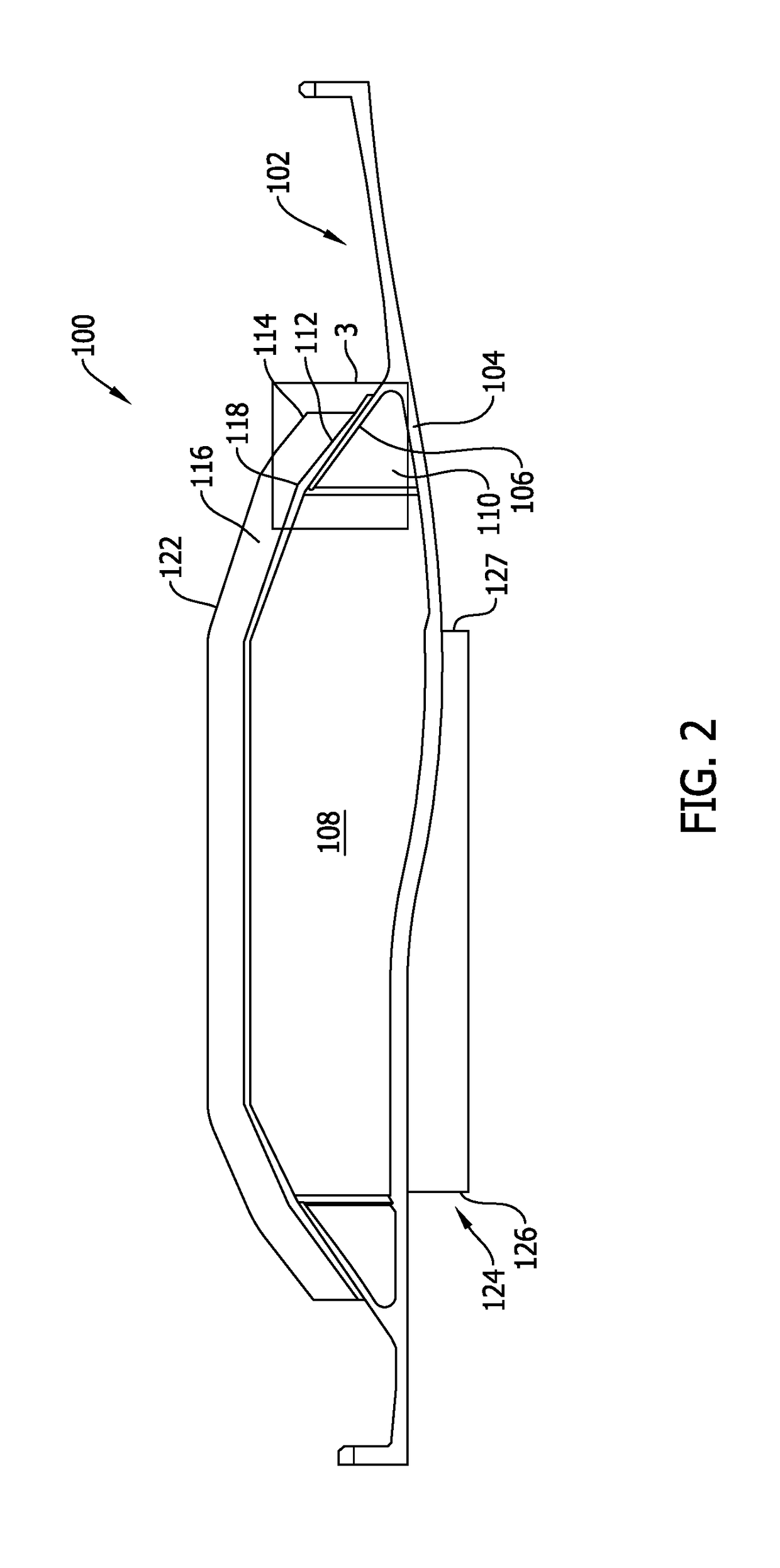
The patent text describes a method to make the angel wing member thinner by forming a notch in it. This helps to make the angel wing member lighter and more flexible.

Problems solved by technology

The thickness of the angel wing member is non-uniform between the base and the tip.

Method used


Image

  • Turbine engine and containment assembly for use in a turbine engine
  • Turbine engine and containment assembly for use in a turbine engine
  • Turbine engine and containment assembly for use in a turbine engine

Examples


Embodiment Construction

[0031]In the following specification and the claims, reference will be made to a number of terms, which shall be defined to have the following meanings.

[0032]The singular forms “a”, “an”, and “the” include plural references unless the context clearly dictates otherwise.

[0033]“Optional” or “optionally” means that the subsequently described event or circumstance may or may not occur, and that the description includes instances where the event occurs and instances where it does not.

[0034]Approximating language, as used herein throughout the specification and claims, may be applied to modify any quantitative representation that could permissibly vary without resulting in a change in the basic function to which it is related. Accordingly, a value modified by a term or terms, such as “about”, “approximately”, and “substantially”, are not to be limited to the precise value specified. In at least some instances, the approximating language may correspond to the precision of an instrument for...


PUM


Abstract

A turbine engine that includes an engine casing including a shell and an angel wing member. The angel wing member includes a base defined at the shell, a tip positioned distal from the base, and a first side and a second side that define a thickness of the angel wing member. The thickness of the angel wing member is non-uniform between the base and the tip.

Description

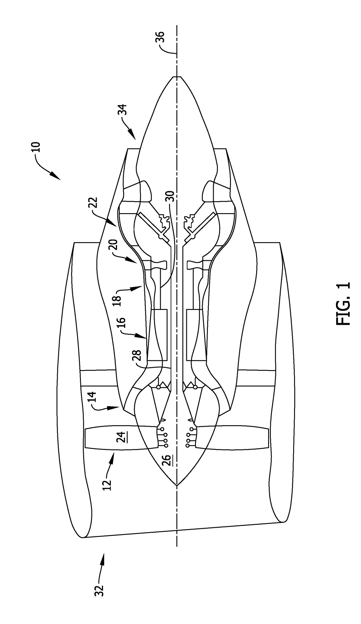
BACKGROUND[0001]The present disclosure relates generally to turbine engines and, more specifically, to a rotor section containment assembly having an improved load path transition between components of the assembly.[0002]At least some known gas turbine engines, such as aircraft engines, include a stator assembly that extends circumferentially about a rotor assembly of the turbine engine. Known rotor assemblies include at least one row of rotor blades that extend radially outward from a blade root, for example, such that the rotor blades rotate proximate the stator assembly of the turbine engine. At least some known stator assemblies include a soft wall containment assembly that facilitates providing rotor containment during unlikely events, such as an unexpected blade-out condition. The soft wall containment assembly generally includes an engine casing, a honeycomb structure coupled to the engine casing, and a carbon fiber backsheet that extends across the honeycomb structure and a ...

Claims


Application Information

Patent Timeline
IPC IPC(8): F04D29/52F04D29/32
CPCF04D29/526F04D29/325F05D2230/60F05D2220/32F05D2250/283F02C3/04F01D25/24F02C3/00F02C7/00F05D2240/14F01D21/045Y02T50/60
Inventor KRAY, NICHOLAS JOSEPHWALDMAN, THOMAS CHADWICKTHOMPSON, JAMES EDWARDWARD, DOUGLASKARAFILLIS, APOSTOLOS PAVLOS
Owner GENERAL ELECTRIC CO
Why Eureka
Eureka Blog
Learn More