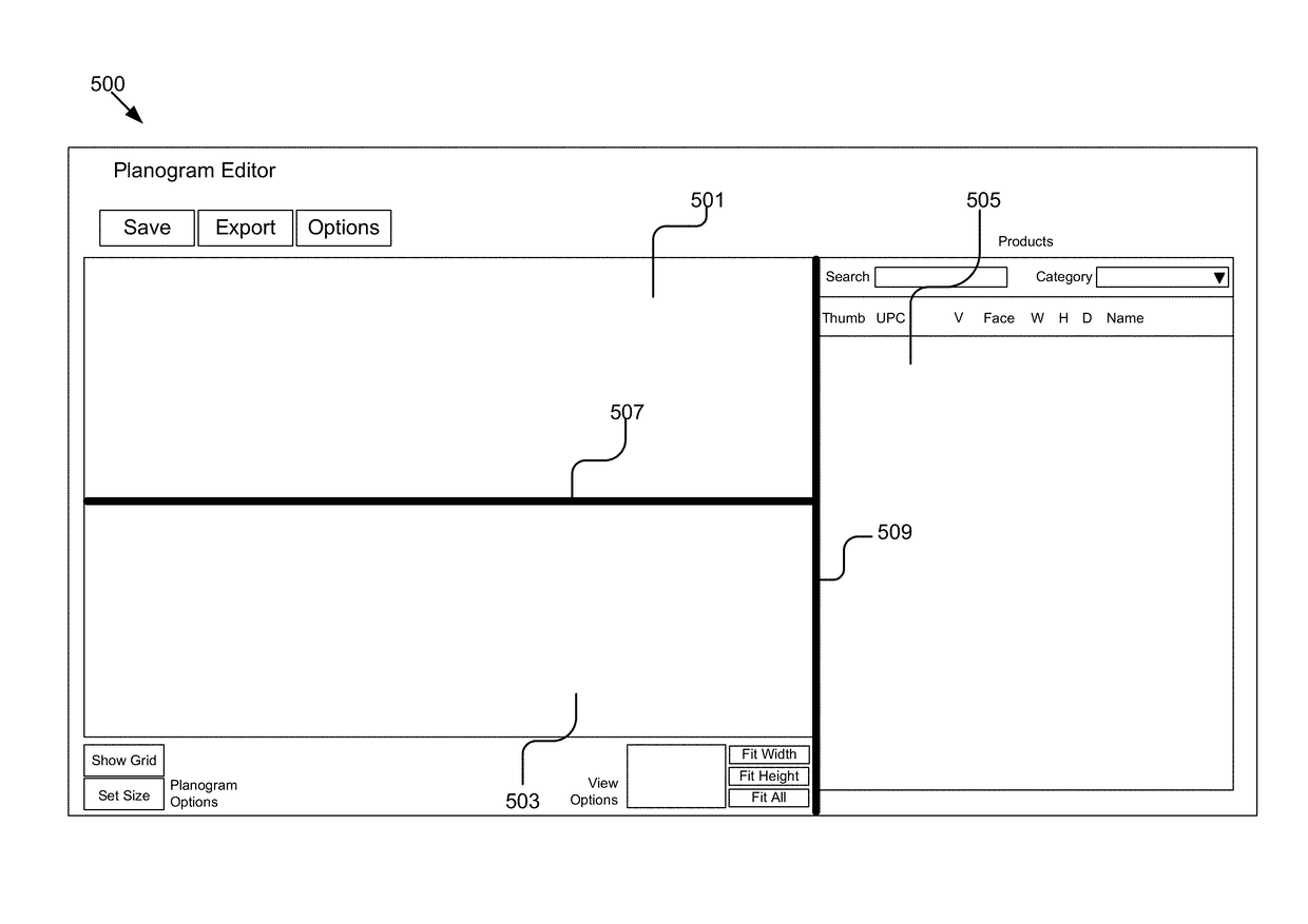
Realogram to Planogram User Interface
a user interface and realogram technology, applied in the field of generating a planogram, can solve the problems of inability to quickly produce planograms, inability to use planograms in some retail situations, and inability to meet the needs of customers,
- Summary
- Abstract
- Description
- Claims
- Application Information
AI Technical Summary
Benefits of technology
Problems solved by technology
Method used
Image

Examples
Embodiment Construction
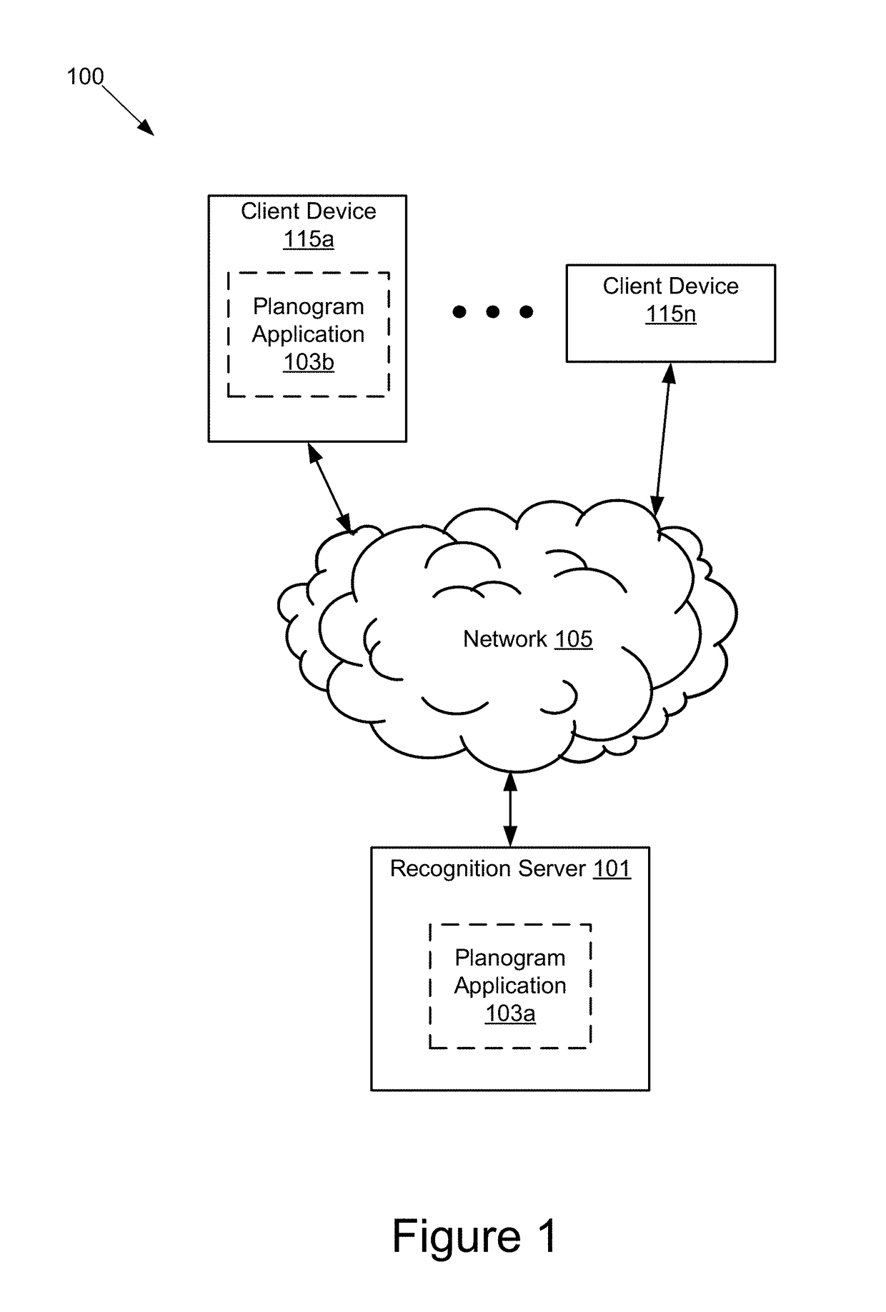
[0018]FIG. 1 is a high-level block diagram illustrating one embodiment of a system 100 for generating a user interface for creating a planogram from a realogram. The illustrated system 100 may have one or more client devices 115a . . . 115n that can be accessed by users and a recognition server 101. In FIG. 1 and the remaining figures, a letter after a reference number, e.g., “115a,” represents a reference to the element having that particular reference number. A reference number in the text without a following letter, e.g., “115,” represents a general reference to instances of the element bearing that reference number. In the illustrated embodiment, these entities of the system 100 are communicatively coupled via a network 105.
[0019]The network 105 can be a conventional type, wired or wireless, and may have numerous different configurations including a star configuration, token ring configuration, or other configurations. Furthermore, the network 105 may include a local area networ...
PUM
 Abstract
Description
Claims
Application Information