Eureka AIR delivers breakthrough ideas for toughest innovation challenges, trusted by R&D personnel around the world.

Fixed-wing aircraft with increased static stability

a technology of static stability and fixed wings, which is applied in the direction of aircrafts, airflow influencers, transportation and packaging, etc., can solve the problems of aircraft stalling, aircraft loss of lift, complex and expensive implementation, etc., and achieves simple, light and inexpensive implementation, the effect of increasing the lift with the vertical componen

Inactive Publication Date: 2018-10-25
DANIELSON AIRCRAFT SYST
View PDF0 Cites 3 Cited by
  • Summary
  • Abstract
  • Description
  • Claims
  • Application Information

AI Technical Summary

Benefits of technology

This patent proposes a fixed-wing aircraft that has increased stability and reduces drag to improve its flight performance and conserve power. It also aims to be a cost-effective and easy-to-design pilotless aircraft that is small in size and can carry a significant payload while requiring a small takeoff and landing strip.

Problems solved by technology

However, this system is complex and expensive to implement so that it is rarely used.
Beyond a certain incidence of the angle of attack of the wing or wings, the aircraft suffers a loss of lift.
This is called stalling of the aircraft.
This phenomenon greatly limits the lift that can be generated for a given speed (a dynamic pressure) and surface area.
However, it has been found that when these solutions are used to increase the lift significantly, they can cause a variation in the angle induced by the horizontal wing or wings with the incidence no longer allowing the horizontal stabilizer to perform its stabilizing function.
Another problem involves the aircraft's induced and parasitic drags, which cause a waste of power.
Moreover, in the field of fixed-wing tactical aircraft, these aircraft have the advantage of being less expensive but with the disadvantage of requiring a relatively long takeoff and landing strip.
However, this type of aircraft has the disadvantage of poor flight autonomy and does not allow a significant payload on board.

Method used


Image

  • Fixed-wing aircraft with increased static stability
  • Fixed-wing aircraft with increased static stability
  • Fixed-wing aircraft with increased static stability

Examples


Embodiment Construction

[0019]One of the purposes of the invention, therefore, is to remedy these disadvantages by proposing a fixed-wing aircraft that has increased static stability under conditions of strong lift, while reducing induced and parasitic drags in order to limit the wastage of power of said aircraft and to increase its flight autonomy.

[0020]Another objective of the invention is to furnish a pilotless aircraft that is inexpensive and simple in design, small in size and with the possibility of carrying a significant payload while needing a takeoff and landing strip of small dimensions.

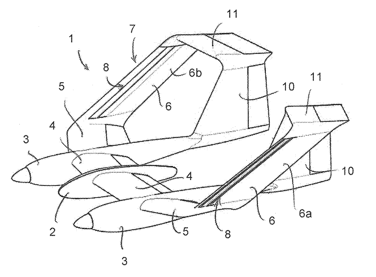
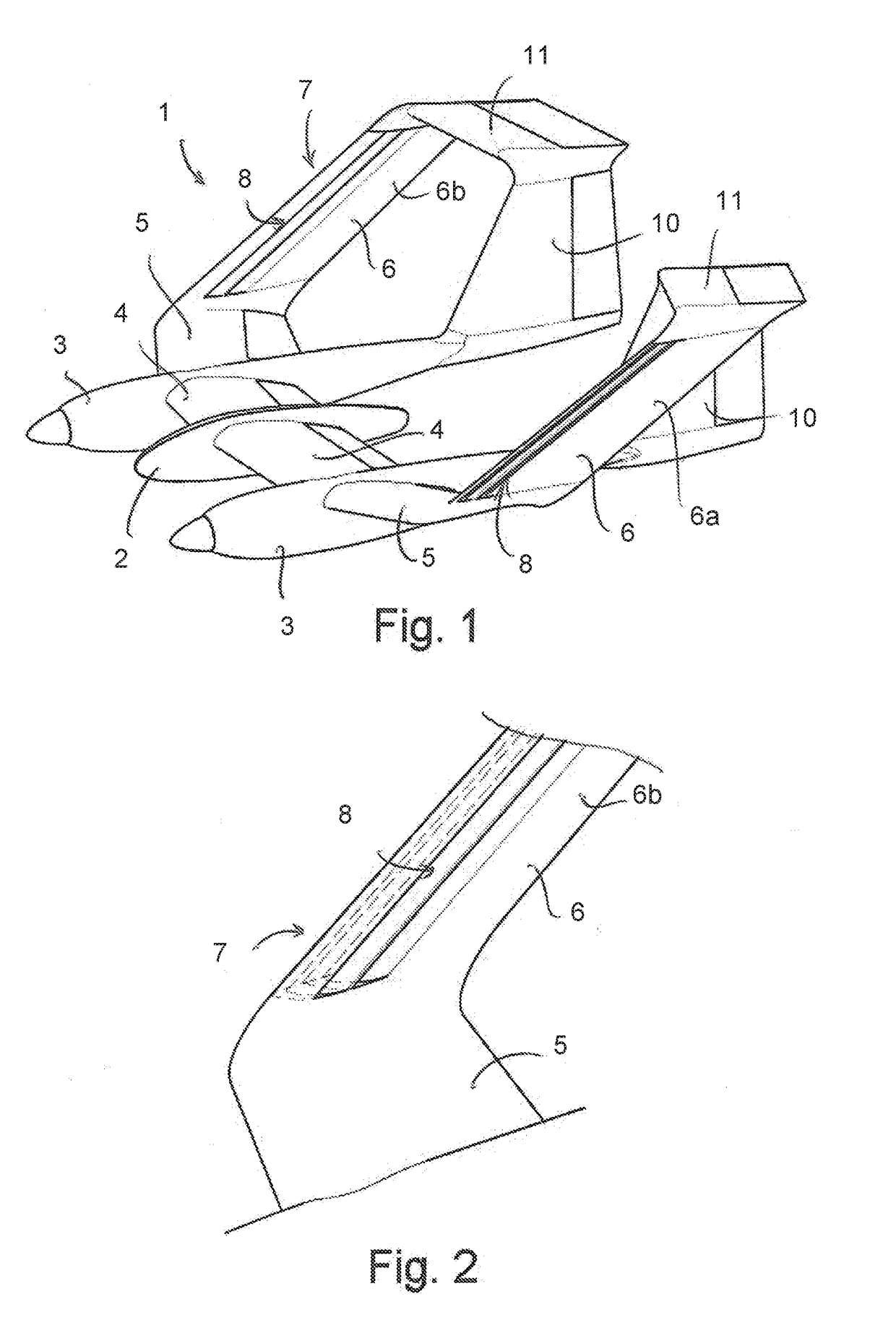
[0021]To that end, and according to the invention, an aircraft is proposed having at least one wing, preferably horizontal, comprising at each of the ends thereof a winglet forming an angle of between 0° and 45° relative to the vertical, and preferably between 1° and 15° relative to the vertical.

[0022]According to the invention, each winglet has a leading edge that comprises at least one slot placed along each lea...


PUM


Abstract

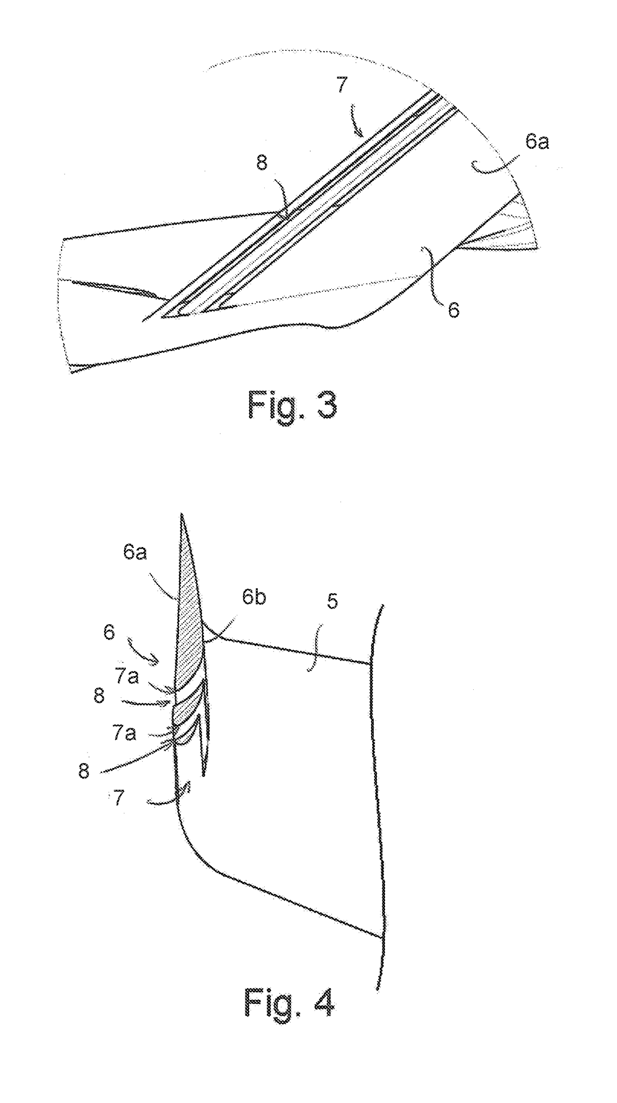
The invention relates to an aircraft having at least one wing (5) including, at each end thereof, a fin (6) forming an angle of between 0° and 45° relative to the vertical. According to the invention, each fin (6) has a leading edge (7) that includes at least one slot (8) provided along said leading edge (7) and oriented so as to cause an air flow to flow via said leading edge (7) from an outer surface (6a) of the fin (6) to an inner surface (6b).

Description

TECHNICAL FIELD[0001]The present invention concerns the technical field of fixed-wing aircraft, such as an airplane or a drone, and more particularly concerns a fixed-wing aircraft with increased static stability.[0002]Drone is understood as being a pilotless aircraft, commonly called drone or UAV for “Unmanned Aerial Vehicle” or UAS for “Unmanned Aerial System.”[0003]Longitudinal static stability is understood as the ability of the aircraft to counter a disruptive pitching movement. In other words, if the aircraft pitches up or down under the effect of a disruptive action, an opposing, inverse torque should be exerted on said aircraft in order to compensate for the angular displacement caused by the disruptive action, pushing the aircraft to resume an equilibrium position of close to the initial position. Longitudinal static stability is highly desirable to make the aircraft pilotable.PRIOR ART[0004]According to the state of the art, a fixed-wing aircraft is known comprising at lea...

Claims


Application Information

Patent Timeline
Patent Type & Authority Applications(United States)
IPC IPC(8): B64C39/06B64C21/02B64C23/06
CPCB64C39/068B64C21/02B64C23/076B64C2230/20B64C2201/021B64C2230/08Y02T50/10B64U30/10B64U10/25
Inventor HUBSCHWERLEN, FREDERIC
Owner DANIELSON AIRCRAFT SYST
Why Eureka
Eureka Blog
Learn More