Near-field communication antenna device and electronic device having same

a communication antenna and near-field technology, applied in the structure of radiating elements, near-field systems using receivers, transmission, etc., can solve the problems of high propagation loss, achieve the effect of preventing radio interference, minimizing channel frequency cross-talk, and improving the transmission/reception efficiency of near-field (short-range) communication

Active Publication Date: 2018-10-25
SAMSUNG ELECTRONICS CO LTD
View PDF20 Cites 6 Cited by
  • Summary
  • Abstract
  • Description
  • Claims
  • Application Information

AI Technical Summary

Benefits of technology

[0011]According to various embodiments of the present disclosure,
[0022]it is possible to improve the transmission / reception efficiency of near-field (short-range) communication by configuring first and second dielectric bodies that are physically and directly connected to transmitting and receiving modules of a near-field (short-range) communication module, and it is possible to minimize cross-talk of channel frequencies by preventing radio interference. In addition, the first and second dielectric bodies are formed integrally with a cover unit of an electronic device to thus improve the fixing force to the electronic device, and the first and second dielectric bodies can be provided in a narrow space in the electronic device, thereby enabling the reduction in the size of the product and slimness thereof and improving the portability of the product.
[0023]Furthermore, since the first and second dielectric bodies can be configured to have various relative-dielectric constants different from each other, it is possible to implement the same to be divided into two or more channel frequency regions, thereby separating the channel frequencies and reducing inter-channel frequency interference.

Problems solved by technology

The near-field (short-range) communication antenna device has a wireless communication distance of only a few tens of millimeters (mm) between wireless portable electronic devices because it has a high propagation loss per unit distance at a high frequency for high-speed data communication.

Method used


Image

  • Near-field communication antenna device and electronic device having same
  • Near-field communication antenna device and electronic device having same
  • Near-field communication antenna device and electronic device having same

Examples


Embodiment Construction

Technical Problem

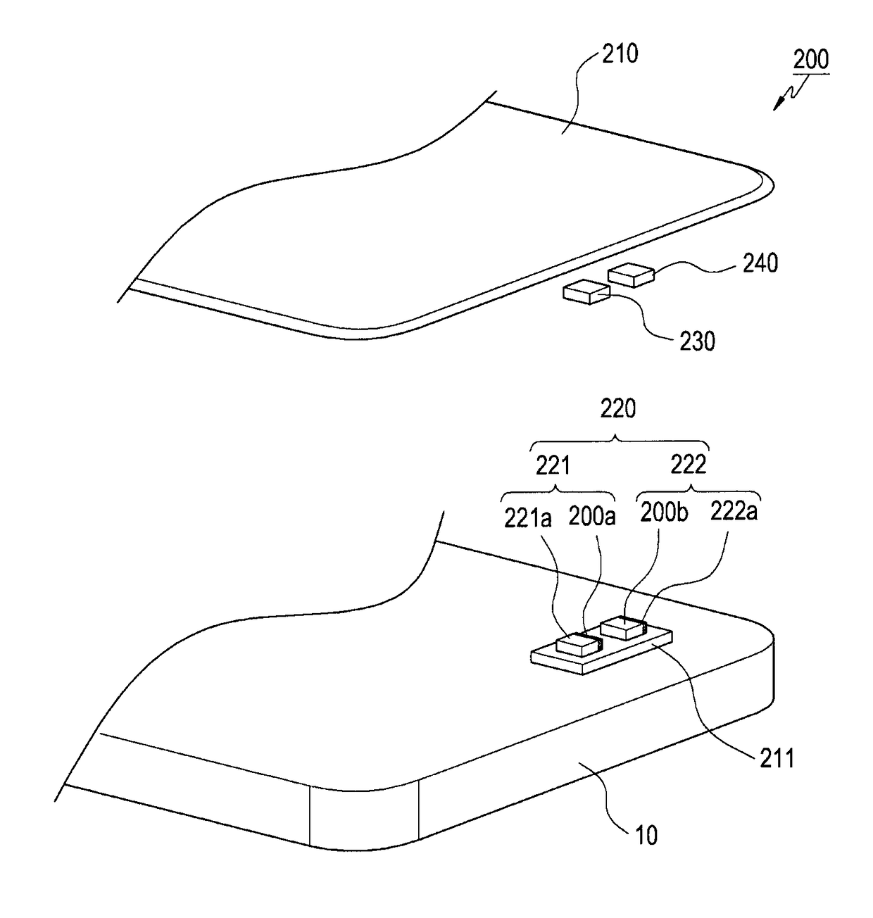
[0007]However, since the conventional near-field (short-range) communication antenna devices require a very short distance between portable electronic devices in order to maintain a radio channel, two portable electronic devices actually performing ultra-high speed near-field (short-range) wireless communication must remain close enough to come into contact with each other for securing the radio channel.

[0008]That is, the near-field (short-range) communication antenna devices in portable electronic devices must be mechanically and accurately aligned with each another in order to maintain a proper communication channel, and if the electronic devices are not accurately aligned, so that the directions of radiation patterns of the near-field (short-range) communication antenna devices mismatch each other, communication efficiency drastically deteriorates.

[0009]Accordingly, in order to cope with the above problems, there is a need to improve the communication performance...


PUM


Abstract

Various embodiments related to a near-field (short-range) communication antenna device, which is used for an electronic device, are disclosed. According to an embodiment, a near-field (short-range) communication antenna device may comprise: an electronic device cover unit; a circuit board provided inside the cover unit; a near-field (short-range) communication module, which is mounted on the circuit board, and which comprises a transmitting module and a receiving module; and first and second dielectric body units that face the transmitting module and the receiving module. In addition, various other embodiments are possible.

Description

TECHNICAL FIELD[0001]Various embodiments of the present disclosure relate to an electronic device adopting a near-field (short-range) communication antenna device.BACKGROUND ART[0002]Near-field (short-range) communication is a generic term encompassing near-field (short-range) wireless personal area network (WPAN) technologies, standards, and products for realizing bidirectional near-field (short-range) communication between portable devices at low cost without complicated cables, and is one of the key technologies of a near-field (short-range) wireless personal area network such as ultra-wide band (UWB) communication technology and ZigBee communication technology.[0003]Near-field (short-range) communication is widely used in portable devices such as mobile phones, headsets, and the like. Near-field (short-range) communication chips implementing near-field (short-range) communication technology are small and inexpensive and have low power consumption, thereby enabling wireless conne...

Claims


Application Information

Patent Timeline
Patent Type & Authority Applications(United States)
IPC IPC(8): H01Q1/24H01Q1/38H01Q13/08H04B5/06
CPCH01Q1/241H01Q1/38H01Q13/08H04B5/06H01Q1/2283H01Q1/243H01Q1/42H01Q9/0485H04B5/0025H04B5/02
Inventor JEON, SEUNG-GILKIM, HYEONG-TAEPARK, JUNG-SIK
Owner SAMSUNG ELECTRONICS CO LTD
Why Eureka
Try Eureka