Additive printing apparatus and method employing liquid bridge

a printing apparatus and liquid bridge technology, applied in the field of additive printing apparatus and methods, can solve the problems of limited sl vat system and limited production structure of sl techniques

Inactive Publication Date: 2018-11-01
CHOI JAE WON +1
View PDF0 Cites 19 Cited by
  • Summary
  • Abstract
  • Description
  • Claims
  • Application Information

AI Technical Summary

Benefits of technology

[0022]In a sixteenth embodiment, the present invention provides an additive printing apparatus as in any of the forgoing embodiments, further comprising a ventilated enclosure enclosing the light source and the light transmissive substrate and the liquid bridge to avoid contamination.

Problems solved by technology

Unfortunately, μSL techniques are typically limited by over curing and the lack of depth control for curing.
Furthermore, all vat systems use large amounts of a photopolymer relatively to the structure that has been created.
Finally, the μSL vat systems are also limited in producing structures with large horizontal areas.

Method used


Image

  • Additive printing apparatus and method employing liquid bridge
  • Additive printing apparatus and method employing liquid bridge
  • Additive printing apparatus and method employing liquid bridge

Examples


Embodiment Construction

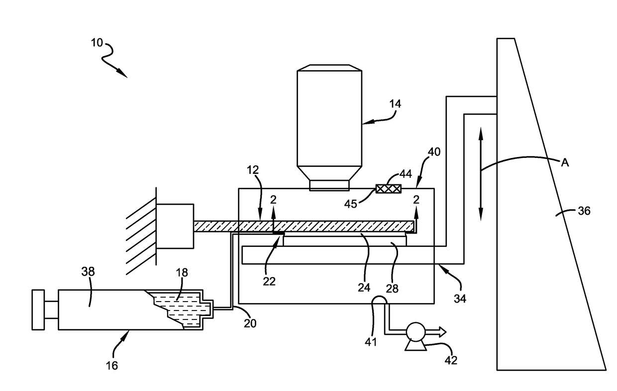
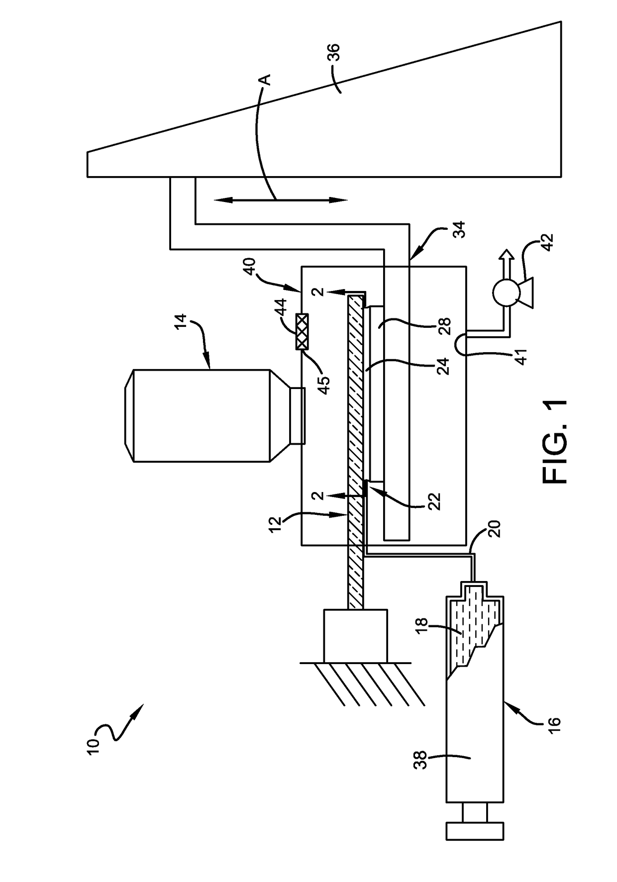
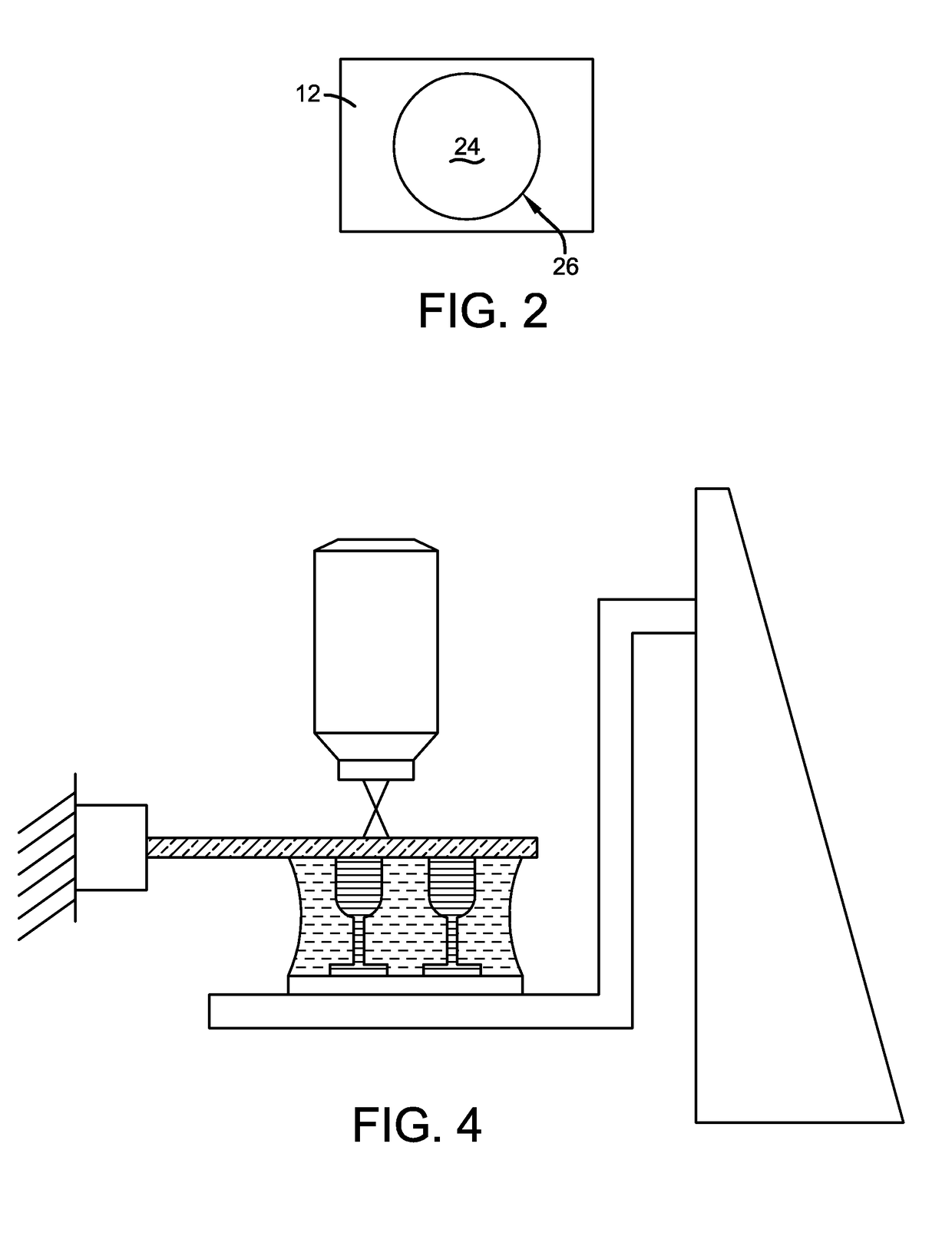
[0045]Referring now to FIG. 1, an additive printing apparatus in accordance with this invention is shown and designated by the numeral 10. The additive printing apparatus 10 includes a light transmissive substrate 12 and a light source 14 adapted to direct light through the light transmissive substrate 12. A photopolymerizable material source 16 supplies a photopolymerizable material 18 for delivery along a fluid path 20 to a delivery position 22 proximate the light transmissive substrate 12. The photopolymerizable material 18 forms a liquid bridge 24 (also known as a capillary bridge or liquid capillary bridge) with the light transmissive substrate 12. As seen in the cross section of FIG. 2, the liquid bridge 24 defines an area of contact 26 with the light transmissive substrate 12. With this minimal structure, additive printing can be achieved by transmitting light through the light transmissive substrate 12 to initiate polymerization of at least a portion of the polymerizable mat...


PUM

PropertyMeasurementUnit
viscosityaaaaaaaaaa
lengthaaaaaaaaaa
heightaaaaaaaaaa

Abstract

An additive printing apparatus includes a light transmissive substrate, a light source adapted to direct light through the light transmissive substrate, a photopolymerizable material source providing photopolymerizable material, and a fluid path from the photopolymerizable material source to a delivery position proximate the light transmissive substrate. Material is delivered through the fluid path the delivery position to form a liquid bridge of the photopolymerizable material, the liquid bridge having an area of contact with the light transmissive substrate, such that, in a method of additive printing, photopolymerizing light can be shone through the light transmissive substrate to polymerize the photopolymerizable material.

Description

CROSS-REFERENCE TO RELATED APPLICATIONS[0001]This application claims the benefit of U.S. Provisional Application No. 62 / 248,730, filed Oct. 30, 2015, and incorporated herein by reference.FIELD OF THE INVENTION[0002]The present invention generally relates to additive printing apparatus and methods. More particularly, the present invention relates to additive printing apparatus and methods employing a liquid bridge to position material for forming an additive printed product layer.BACKGROUND OF THE INVENTION[0003]Current technology for microstereolithography (μSL) employs a vat to provide the polymer, photoinitiator, and additives to create 3D microstructures using photopolymerization (Choi et al., Design of Microstereolithography System Based on Dynamic Image Projection for Fabrication of Three-Dimensional Microstructures, Journal of Mechanical Science and Technology, Vol. 20, No. 12, pages 2120-2130, 2006); Choi, et al., Cure depth control for complex 3D microstructure fabrication i...

Claims


Application Information

Patent Timeline
Patent Type & Authority Applications(United States)
IPC IPC(8): B29C64/20B33Y10/00B33Y30/00B29C64/124
CPCB29C64/20B33Y10/00B33Y30/00B29C64/124B29C64/264
Inventor CHOI, JAE-WONYUN, YANG H.
Owner CHOI JAE WON
Why Eureka
Try Eureka