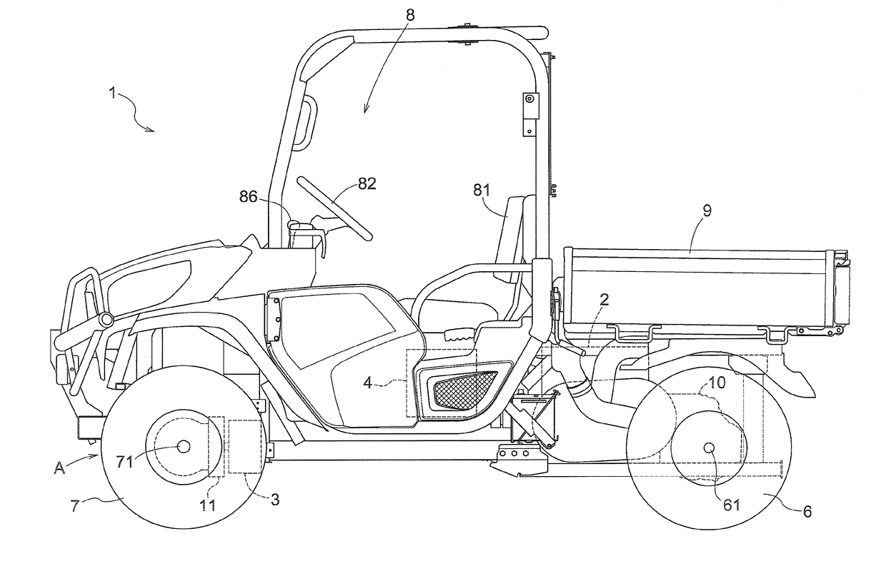
Multi-Purpose Vehicle
a multi-purpose vehicle and vehicle technology, applied in the direction of electric propulsion mounting, vehicle sub-unit features, gearing, etc., can solve the problems of high fuel consumption and problematic multi-purpose vehicles
- Summary
- Abstract
- Description
- Claims
- Application Information
AI Technical Summary
Benefits of technology
Problems solved by technology
Method used
Image
Examples
case c2
Case C2
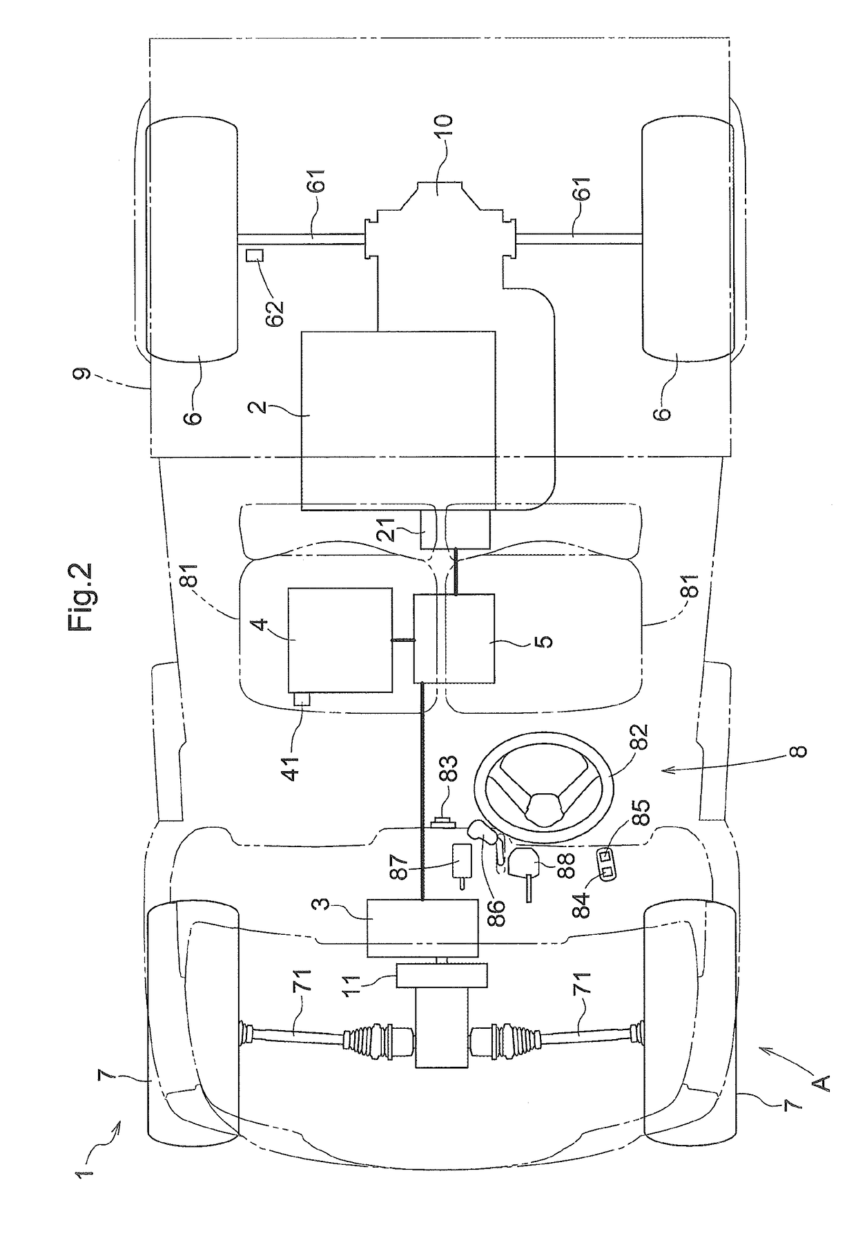
[0121]Next, a case C2 will be described in which the key switch 83 is moved from the OFF-position P1 to the start position P3 in a state in which the travel mode is in the OFF-mode M1, and the charge rate of the battery 4 is higher than a predetermined charge rate S, and thereafter the mode switch button 84 is pressed, without the charge mode button 85 being pressed, and then the key switch 83 is moved from the ON-position P2 to the OFF-position P1.
[0122]In the flow of processing in the case C2, the processing from step S1 to step S4 is the same as that of the case C1. Accordingly, the processing performed after the procedure has transitioned from step S4 to step S5 will be described.
[0123]In step S5, it is determined whether or not the mode switch button 84 has been pressed. In the case C2, the mode switch button 84 is pressed (YES), and thus the travel mode is switched from the four-wheel hybrid driving mode M4 to the two-wheel motor driving mode M2 by the mode control devi...
case c3
Case C3
[0128]Next, a case C3 will be described in which the key switch 83 is moved from the OFF-position P1 to the start position P3 in a state in which the travel mode is in the OFF-mode M1, and the charge rate of the battery 4 is higher than a predetermined charge rate S, thereafter the charge mode button 85 is pressed without the mode switch button 84 being pressed, and then the key switch 83 is moved from the ON-position P2 to the OFF-position P1 without the mode switch button 84 being pressed.
[0129]In the flow of processing in the case C3, the processing from step S1 to step S3 is the same as that of the case C1. Accordingly, the processing performed after YES has been determined in step S3 will be described.
[0130]If YES is determined in step S3, the travel mode is switched from the two-wheel motor driving mode M2 to the four-wheel hybrid driving mode M4 by the mode control device 91. After that, the procedure transitions to step S4.
[0131]In the case C3, the processing in steps...
case c4
Case C4
[0138]Next, a case C4 will be described in which the key switch 83 is moved from the OFF-position P1 to the start position P3 in a state in which the travel mode is in the OFF-mode M1, and the charge rate of the battery 4 is higher than a predetermined charge rate S, thereafter the charge mode button 85 is pressed without the mode switch button 84 being pressed, then the mode switch button 84 is pressed, and thereafter the key switch 83 is moved from the ON-position P2 to the OFF-position P1.
[0139]In the flow of processing in the case C4, the processing from step S1 to step S4 is the same as that of the case C3. Accordingly, the processing performed after YES has been determined in step S4 will be described.
[0140]If YES is determined in step S4, the travel mode is switched from the four-wheel hybrid driving mode M4 to the two-wheel engine driving mode M3 by the mode control device 91. After that, the procedure transitions to step S8.
[0141]In step S8, it is determined whether ...
PUM
 Abstract
Description
Claims
Application Information
 - R&D
- Intellectual Property
- Life Sciences
- Materials
- Tech Scout
- Unparalleled Data Quality
- Higher Quality Content
- 60% Fewer Hallucinations
Browse by: Latest US Patents, China's latest patents, Technical Efficacy Thesaurus, Application Domain, Technology Topic, Popular Technical Reports.
© 2025 PatSnap. All rights reserved.Legal|Privacy policy|Modern Slavery Act Transparency Statement|Sitemap|About US| Contact US: help@patsnap.com


