Magnetic connecting member, in particular for pipe flanges

a technology of magnetic connection and flange, which is applied in the direction of flanged joints, pipe/joints/fittings, pipe-joints, etc., can solve the problem of relatively complicated arrangement of these couplings

Active Publication Date: 2018-11-01
CUBER PETR
View PDF15 Cites 3 Cited by
  • Summary
  • Abstract
  • Description
  • Claims
  • Application Information

AI Technical Summary

Benefits of technology

[0018]The invention allows quick and reliable connection of interconnected channels and if needed, also easy disconnection. It will find its application particularly in the field of gas engineering and power engineering as a means for connection of various types of pipeline with gas in explosive environment, where control by means of electric current cannot be used because of explosion due to possible spark, and also as a quick-coupling device. The invention can be utilized for cogeneration units, for highly flammable liquid tanks, as a quick-coupling device for water conduit e.g. for fire fighters, for connection of pipeline with chemicals, and also for couplings in food industry. The advantages of the invention include possibility of easy manual control even for large-capacity equipment, independence on electricity, hygienic configuration without contact with ambient environment. The independence on electricity brings another advantage in that the connection can be used and its connection / disconnection can be controlled even during a power failure. Significant advantages are represented also by that the connection strength can be adjusted at the site according to the calculation of actual demand, and that the magnets in the device can be replaced, for example with stronger or weaker or new ones in case of material fatigue, or optionally cumulated. Other advantage of the invention is possibility of versions from various materials such as stainless steel, ceramics, and plastics.
[0019]The invention is illustrated using drawings, where FIGS. 1 to 6 show magnetic connecting member according to the first example of embodiment and FIGS. 7 to 12 show magnetic connecting member according to the second example of embodiment, of which
[0020]FIG. 1 shows perspective view of magnetic connecting member according to the first example of embodiment,
[0021]FIG. 2 shows perspective view on the same in partially disassembled state,
[0022]FIG. 3 shows side view on the same in a disassembled state,
[0023]FIG. 4 shows side view of vertical section drawn along the line A-A indicated on the following figure, across the centre of the same connecting member, however with the upper flange cut off, with illustration of clamp fastening and arrangement of pit with passage channel before placing the magnet as well as after placing the magnet,

Problems solved by technology

The magnets are placed in these couplings perpendicularly to the axis of rotation of the rotating part, the arrangement of these couplings is relatively complicated and generally works only in combination with electric control, their technical solution does not relate in any way to the solution proposed hereinafter.

Method used


Image

  • Magnetic connecting member, in particular for pipe flanges
  • Magnetic connecting member, in particular for pipe flanges
  • Magnetic connecting member, in particular for pipe flanges

Examples


example 1

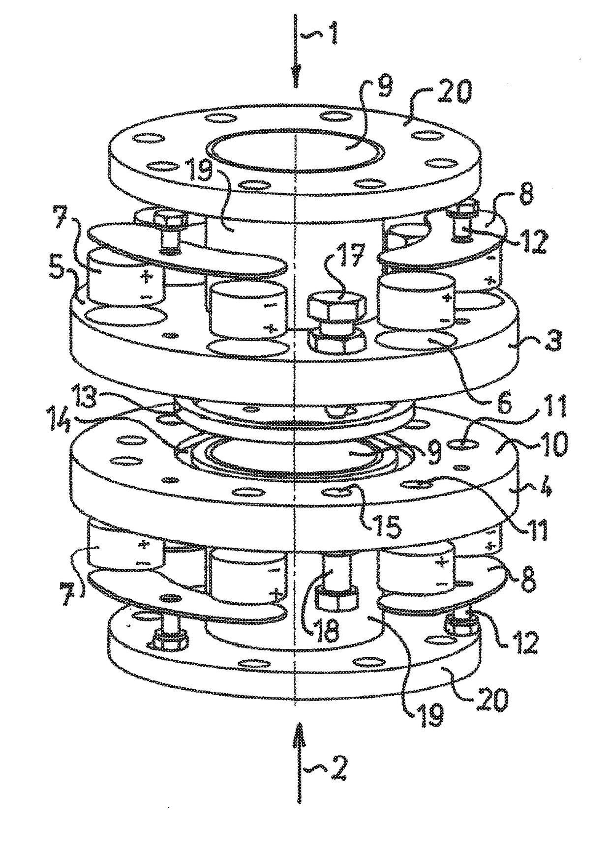
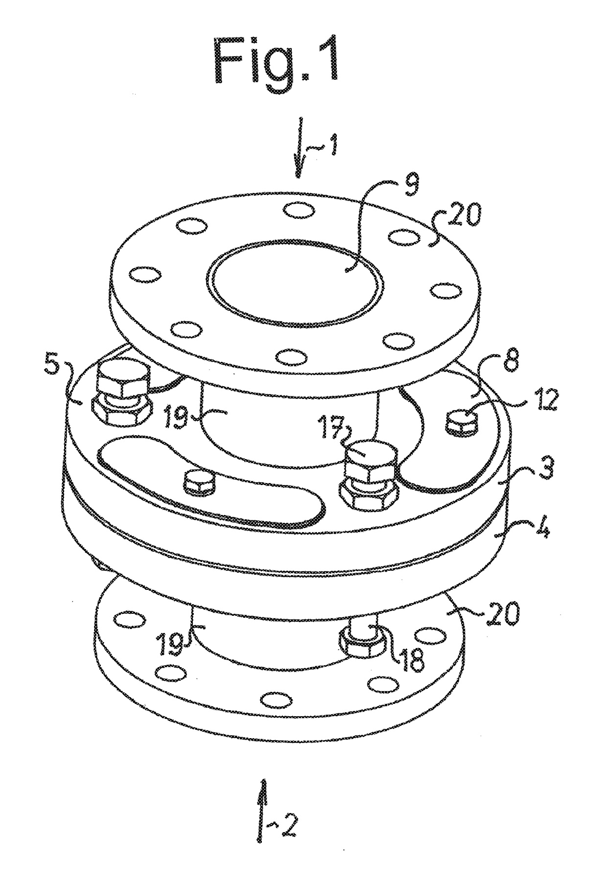
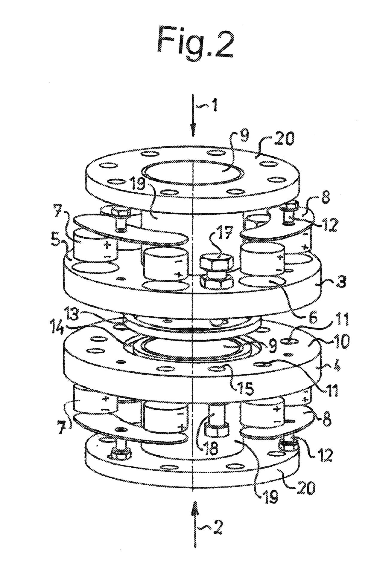
[0032]Example of the best embodiment of the invention for interconnection of two pipelines or one pipeline and a vessel or two vessels to one another is the magnetic connecting member for pipe flanges according to FIGS. 1 to 6.

[0033]This connecting member is intended for insertion and connection between the pipeline or vessel flanges not shown on figures. Accordingly, it is intended for interconnection of cavities for flow of media, which are situated inside a pipe or inside an outlet from a vessel. The contact part of the connection for the ends of channels 1, 2 being connected to one another is created by connecting plates 3, 4 of nonmagnetic material, for example special nonmagnetic steel or composite based on resins or plastics. Their backsides 5 are equipped with set of pits 6 with magnets 7 covered with clamps 8. In this particular case, six pits 6 are situated in each of the connecting plates 3, 4. The pits 6 are equipped with in them placed polarized permanent magnets 7 cove...

example 2

[0041]This example shows the best embodiment of the invention in the case of required interconnection of more than two pipelines and simultaneously in the case of need to connect the pipeline through a closing device 21. For these requirements, the magnetic connecting member is designed according to FIGS. 7 to 12.

[0042]Many elements are similar or the same as those described in the previous example. This magnetic connecting member also includes connecting plates 3, 4 having on their backsides 5 sets of pits 6 with magnets 7. Similarly, passage channels 11 are running out from the pits 6, passing through the remaining thickness of the connecting plate 3, 4 and leading to the opposite side of the connecting plate 3, 4 on its flat and smooth front surface 10.

[0043]In contrast to the previous example, the connecting plates 3, 4 have more passages 91, 92 created and therefore they are adequately enlarged as compared to the previous example and they are even enriched with additional eleme...


PUM


Abstract

Pair of connecting plates contain on the backside pits fitted with magnets, while at the “connected” position the connecting plates are adjacent, they have identical axially oriented polarization. The pits have passage channels and are laid-out on imaginary circles, where the neighbouring magnets have alternating polarization and by pairs and / or threes are covered with magnetic hasps fitted with hasp screws. Centring and disconnection are ensured with the help of centring holes, and possibly centring dimples, fitted with connecting / disconnecting devices. Additional passages placed between two circles with magnets can be added. Possible closing device is attached by spacing posts, spacing screws and ring.

Description

TECHNICAL FIELD[0001]The invention relates to the arrangement of magnetic connecting member intended for coupling of pipeline sections, particularly for pipeline flanges, or for connection of containers or for connection of vessels to the pipeline.BACKGROUND ART[0002]Currently, classic flanges are used for coupling of pipeline parts and for disconnectable connection of vessels, containers, tanks or other hollow chambers to a pipeline. These are cases of fitting with a plate in the shape of a flat ring, firmly fixed at the end of connected piping section, which is equipped with holes or thread, by means of which always two corresponding counterparts are fixed to each other.[0003]The use of magnets for various purposes is known in technics. Magnets are often part of various holders, in which one or more magnets are fitted in / on the surface area of the holder as a component, to which by mere attaching various metal objects can be fastened on the holder. Furthermore, magnets are used fo...

Claims


Application Information

Patent Timeline
Patent Type & Authority Applications(United States)
IPC IPC(8): F16L23/036F16L37/00F16L23/00
CPCF16L23/036F16L37/004F16L23/003F16B2200/83F16L23/00
Inventor CUBER, PETRPULLMANOVA, MONIKA
Owner CUBER PETR
Why Eureka
Try Eureka