Magnet assembly for MRI comprising cylindrical rings of halbach type

a technology of halbach type and cylindrical rings, which is applied in the field of halbach type cylindrical rings of magnet assembly, can solve the problems of increasing the size and weight of the magnet, increasing the complexity and empirical effect of the shimming procedure, and increasing the amount of magnetic materials, so as to reduce the effect of the finite length of the magn

Active Publication Date: 2018-11-01
SOTGIU ANTONELLO
View PDF1 Cites 10 Cited by
  • Summary
  • Abstract
  • Description
  • Claims
  • Application Information

AI Technical Summary

Benefits of technology

[0008]The present invention identifies the methods of construction and shimming of a magnet for clinical application built using Halbach rings to obtain a homogeneous field in a region, internal to the magnet, of linear dimensions equal to about 40% of the size of the magnet. The rings are assembled using blocks of identical size, magnetized along a direction perpendicular to one of the side surfaces of the blocks. The whole magnet consists of 6 Halbach rings each composed of 16 identical blocks as shown in FIG. 1a and FIG. 1b. The magnetized blocks have a cylindrical shape in which the base is a regular hexadecagon (or a prism with hexadecagon base) (FIG. 3). The direction of magnetization is perpendicular to the cylinder axis and directed towa...

Problems solved by technology

The presence of the yoke and of the iron pole has the following drawbacks:Iron introduces magnetic losses, and this requires a greater amount of magnetic material to generate a given magnetic field;It greatly increases size and weight of the magnet;The shimming procedure becomes more complex and empirical due to the non-linearity of the iron magnetic susceptibility.
The case of FIG. 2a implies a magnetic treatment of the entire ring which is technologically impractical particularly for a large magnetic device.
This is also difficult to obtain since the dimension of the blocks a...

Method used


Image

  • Magnet assembly for MRI comprising cylindrical rings of halbach type
  • Magnet assembly for MRI comprising cylindrical rings of halbach type
  • Magnet assembly for MRI comprising cylindrical rings of halbach type

Examples


Embodiment Construction

: MAGNET CONSTRUCTION

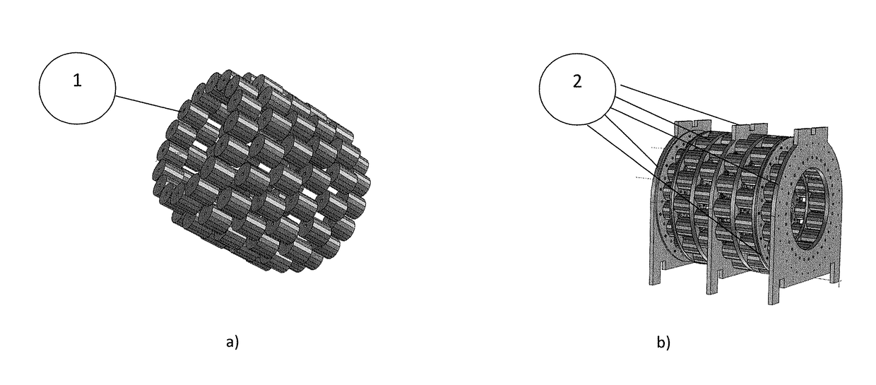
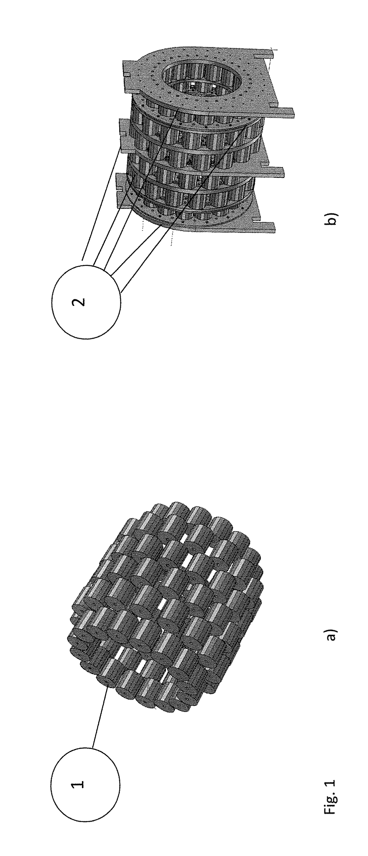
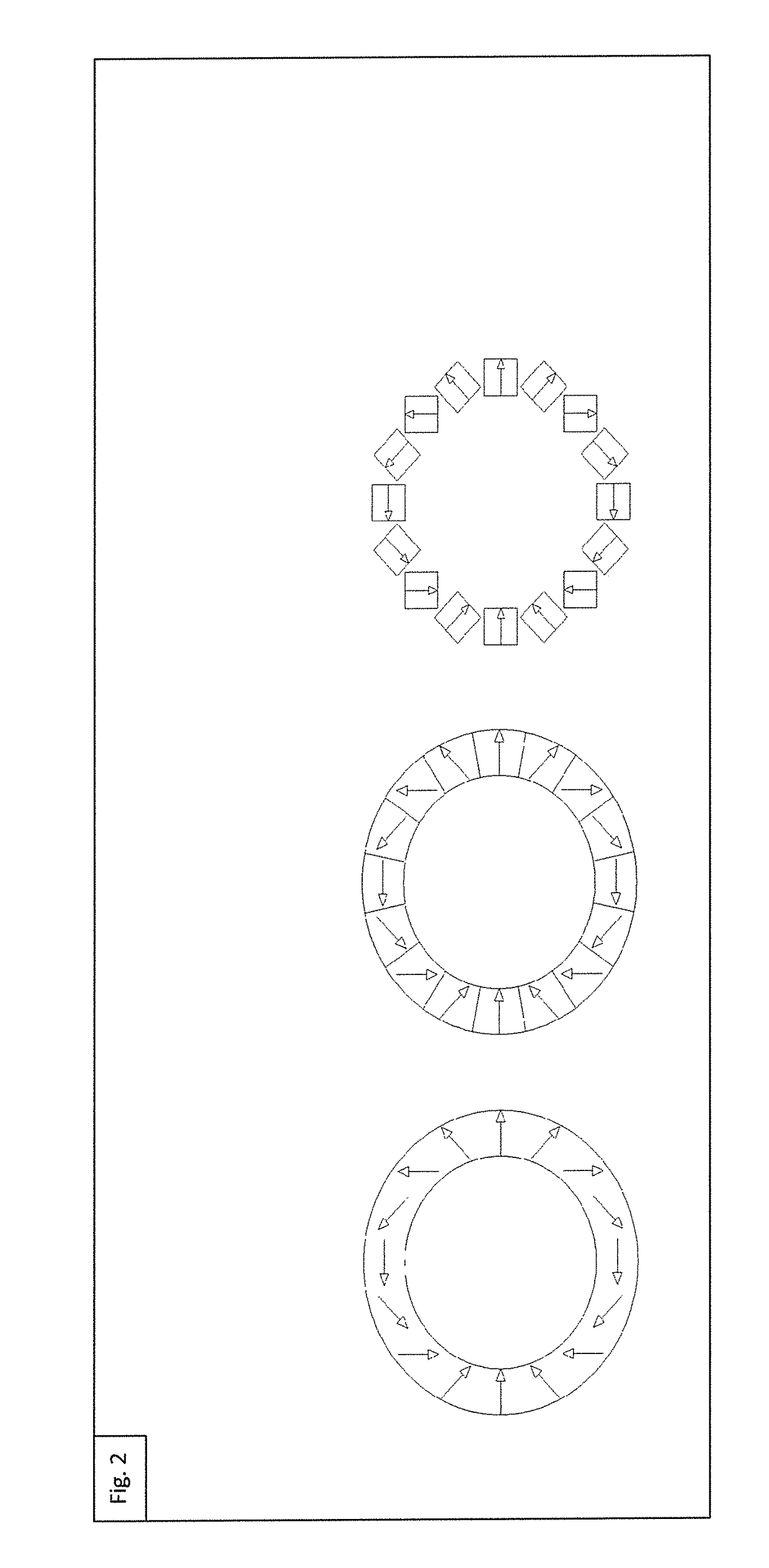
[0032]The magnet, whose preferred embodiment is shown in FIG. 1, is formed by 6 Halbach rings divided into two subgroups, the inner rings (2) and the two outer rings (1). Each ring has 16 blocks of cylindrical shape with hexadecagonal base (FIG. 1). The magnetization of the blocks is perpendicular to the cylinder axis and directed towards the center of one of the faces. The orientation of the magnetization of the rings is such as to perform a rotation of 720° within one revolution. A magnet located in the angular position α will therefore have an orientation of magnetization equal to 2*α.

[0033]As shown in FIG. 4 the inner rings have the same radius while the end rings are placed at a smaller distance so as to partially compensate for the effect of the finite length of the magnet. The supports that hold the magnet are aluminum. The rotation of the magnetization on each ring confines the magnetic field within the magnet and does not need an iron structure nor as a...


PUM


Abstract

Construction methods and techniques allow for a magnetic field of the field homogeneity required for the use in magnetic resonance imaging (MRI), in the order of 20 parts per million (ppm) in the area of interest (such techniques in the following will be indicated with the word “shimming”). The peculiarity of the constructive method is to obtain a homogeneous field region, usable for the MRI analysis, of linear dimensions equal to about 40% of the linear dimensions of the magnet. The shimming technique involves the use of conditioned magnetic material and allows accurate control of the magnetization of the corrective elements while using a material that inherently has a large spread in the magnetization value. The result is a low weight and small magnet suitable for MRI for dedicated clinical applications such as the analysis of the peripheral joint, the analysis of the ocular region, and veterinary applications.

Description

[0001]The present invention identifies the construction methods and the techniques that allow to obtain a magnetic field of the field homogeneity required for the use in magnetic resonance imaging (MRI), in the order of 20 parts per million (ppm) in the area of interest (such techniques in the following will be indicated with the word “shimming”). The peculiarity of the described constructive method is to obtain a homogeneous field region, usable for the MRI analysis, of linear dimensions equal to about 40% of the linear dimensions of the magnet. The shimming technique involves the use of conditioned magnetic material and allows to control accurately the magnetization of the corrective elements while using a material that inherently has a large spread in the magnetization value. The result is a low weight and small magnet suitable for MRI for dedicated clinical applications such as the analysis of the peripheral joint, the analysis of the ocular region, veterinary applications.TECHN...

Claims


Application Information

Patent Timeline
IPC IPC(8): G01R33/383G01R33/3873A61B5/055H01F7/02
CPCG01R33/383G01R33/3873A61B5/055H01F7/0278
Inventor SOTGIU, ANTONELLO
Owner SOTGIU ANTONELLO
Why Eureka
Try Eureka