
Adaptive radiation therapy planning

a radiation therapy treatment and patient technology, applied in radiation therapy, x-ray/gamma-ray/particle irradiation therapy, therapy, etc., can solve the problems of (net) shrinkage of tumor, increased clinical workload associated with re-planning procedure, and high risk of affecting healthy tissue, etc., to achieve efficient generation

Active Publication Date: 2018-11-08
KONINKLJIJKE PHILIPS NV
View PDF0 Cites 1 Cited by
  • Summary
  • Abstract
  • Description
  • Claims
  • Application Information

AI Technical Summary

Benefits of technology

The invention provides a method for generating a treatment plan for a target structure, such as a tumor, that takes into account changes in the delineation of the target structure during the treatment and without the need to adapt the treatment plan during the treatment. The method involves determining an estimate of the delineation of the target structure based on a radiation dose to be applied to the target structure prior to the treatment and expected changes in the target structure resulting from the treatment and other additional treatments, such as chemotherapy. The estimated delineation can be used to select a treatment plan and can improve the accuracy of the treatment plan. The method simplifies the planning procedure and avoids delays resulting from a re-planning during the treatment.

Problems solved by technology

So, a tumor changes due to its natural progression, which normally results in a growth of the tumor, and, most notably, due to the effects of the radiation therapy, which result in a (net) shrinkage of the tumor.
If the original treatment plan generated on the basis of the (stationary) delineation of the tumor or target structure is used after shrinkage of the target structure, there is a high risk to affect healthy tissue by applying a high radiation dose to such tissue.
One drawback of such an adaptive radiation therapy is an increased clinical workload associated with the re-planning procedure, which is usually also made in an operator-guided procedure similar to the generation of the original treatment plan.
This can even lead to delays in the delivery of the radiation treatment, which can compromise the outcome of the radiation therapy, since the maximum impact of the therapy is only achieved when it is delivered sufficiently quickly so that a repopulation of tumor cells is avoided.

Method used


Image

  • Adaptive radiation therapy planning
  • Adaptive radiation therapy planning
  • Adaptive radiation therapy planning

Examples


Embodiment Construction

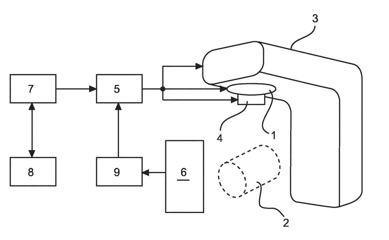
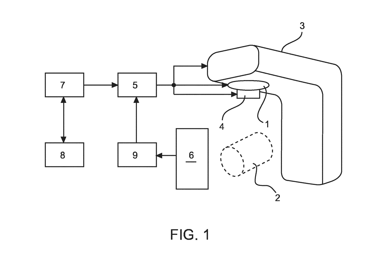
[0032]FIG. 1 schematically and exemplarily illustrates an embodiment of a radiation therapy system for delivering radiation treatments to structures within a human or animal patient body. In particular, the system may be used to treat tumors within certain structures of the body. One example of such a structure is the lung as it is known that radiation therapy, particularly so-called stereotactic ablative radiation therapy (SBART), is especially suitable for treating lung cancer. It has been observed that particularly SBART treatment of lung tumors results in noticeable changes of the tumor volume in each treatment fraction. Such changes and similar changes in other radiotherapy treatments can be taken account of by adapting the treatment plan for the radiation therapy treatment as explained herein below.

[0033]In the illustrated embodiment, the radiation therapy system comprises a radiation source 1, which can be operated to emit ionizing radiation to be delivered to a tumor or anot...


PUM


Abstract

The invention relates to a system for generating a radiotherapy treatment plan (33; 34) for treating a target structure within a patient body. The system comprises (i) a modeling unit configured to determine a series of estimates (31a-d; 32a-d) of a delineation of the target structure for consecutive points of time during the radiation therapy treatment on the basis of a model quantifying changes of the delineation with time, and (ii) a planning unit configured to determine the treatment plan (33; 34) on the basis of the series of estimates (31a-d; 32a-d) of the delineation of the target structure. Further, the invention relates to method carried out in the system.

Description

FIELD OF THE INVENTION[0001]The invention generally relates to a planning of an external beam radiation therapy treatment of a patient. More specifically, the invention relates to a system, a method and a computer program for generating a radiotherapy treatment plan for a patient.BACKGROUND OF THE INVENTION[0002]In external beam radiation therapy, ionizing radiation is applied to target structures, such as tumors, within patients' bodies in order to control growth of or kill cancer cells. The radiation treatment is usually delivered in plural sessions, which are also referred to as treatment fractions in the art. In more advanced types of radiation therapy, such as so called intensity-modulated radiation therapy (IMRT), precise doses of radiation are applied to regions of the patient's body. In this respect, it is typically the goal to deliver a sufficiently high radiation dose to the target structure and to spare sensitive structures, such as organs, in the vicinity of the target s...

Claims


Application Information

Patent Timeline
Patent Type & Authority Applications(United States)
IPC IPC(8): A61N5/10
CPCA61N5/1038A61N5/1039A61N5/1045A61N5/1049A61N2005/1041
Inventor DA SILVA RODRIGUES, PEDRO JORGEISOLA, ALFONSO AGATINOTRINDADE RODRIGUES, ANDREIA MARIA ARAUJO
Owner KONINKLJIJKE PHILIPS NV
Learn More