
Combined Current and Voltage Sensor for High Voltage Electric Power Lines

Active Publication Date: 2018-11-08
SOUTHERN STATES
View PDF9 Cites 11 Cited by
  • Summary
  • Abstract
  • Description
  • Claims
  • Application Information

AI Technical Summary

Benefits of technology

The electric power current and voltage monitoring system can measure the electricity usage and send the data to a control center. It has a special shield to protect the antenna from electromagnetic interference. The system has a reliable communication system with two antenna elements that work at different polarities. This ensures that the system can communicate with high reliability even if there are interference sources nearby.

Problems solved by technology

Conventional CTs are often placed in physical contact with the monitored power line conductor, which results in excessive heating of the CT and the power line.
Excessive heating can adversely impact electronics in the CT and limit the current carrying capacity of the power line.
Conventional CTs are also limited to electric current measurement, resulting in the need for separate voltage sensors when both current and voltage measurement are desired.
Batteries require periodic maintenance, while low voltage wiring requires a nearby transformer, which increases the cost and maintenance requirements.
Traditional voltage measurement devices, while accurate, are expensive and physically large, which limits the number of electric power circuit locations where they can be cost effectively be deployed.
High voltage sensors are presently available, but the conventional voltage sensing techniques are usually sensitive to electromagnetic interference errors (also referred to as “cross talk” or “contamination”) caused by other high voltage power lines and devices in close proximity.
In addition, many conventional voltage sensors are non-directional, which renders them particularly susceptible to electromagnetic contamination.
Electromagnetic contamination also impairs the measurement of the voltage phase angle, which is critical for VAR measurement, capacitor switching for voltage support, and sophisticated direction-to-fault and distance-to-fault sectionalizing techniques.
However, conventional capacitive foil patch sensors are typically non-directional, which makes them susceptible to significant cross talk from nearby high voltage power lines and devices.
While a line mounted patch sensor with a ground plane positioned adjacent to the power line experiences relatively good coupling to the power line, nearby power lines and other high voltage devices, such as disconnect switches and equipment bushings, can still cause significant cross talk.
However, conductive shielding can be physically challenging to design and mathematical filtering is complicated by variations in capacitance caused by changing environmental factors.
Power line conductors experience physical sag, which can be significantly impacted by the ambient temperature.
While the majority of these effects can be compensated for by measuring the temperature of the local mechanical support and using a calibration table to account for these changes in capacitance, this increases the cost and complexity of the measurement system.
Moreover, temperature compensation may not be sufficient in some cases because sensor performance can also vary significantly due to the surface condition of the physical sensor support.
These parasitic effects are caused by a resistive layer, such as water, ice, oxidation or grime, on the surface of the sensor support or housing.
Resistive surface contamination can significantly change the measured phase angle with respect to the voltage field and reduce the signal magnitude available to measure.
Moisture or high humidity in the ambient air can exasperate these sensor impacts.

Method used


Image

  • Combined Current and Voltage Sensor for High Voltage Electric Power Lines
  • Combined Current and Voltage Sensor for High Voltage Electric Power Lines
  • Combined Current and Voltage Sensor for High Voltage Electric Power Lines

Examples


Embodiment Construction

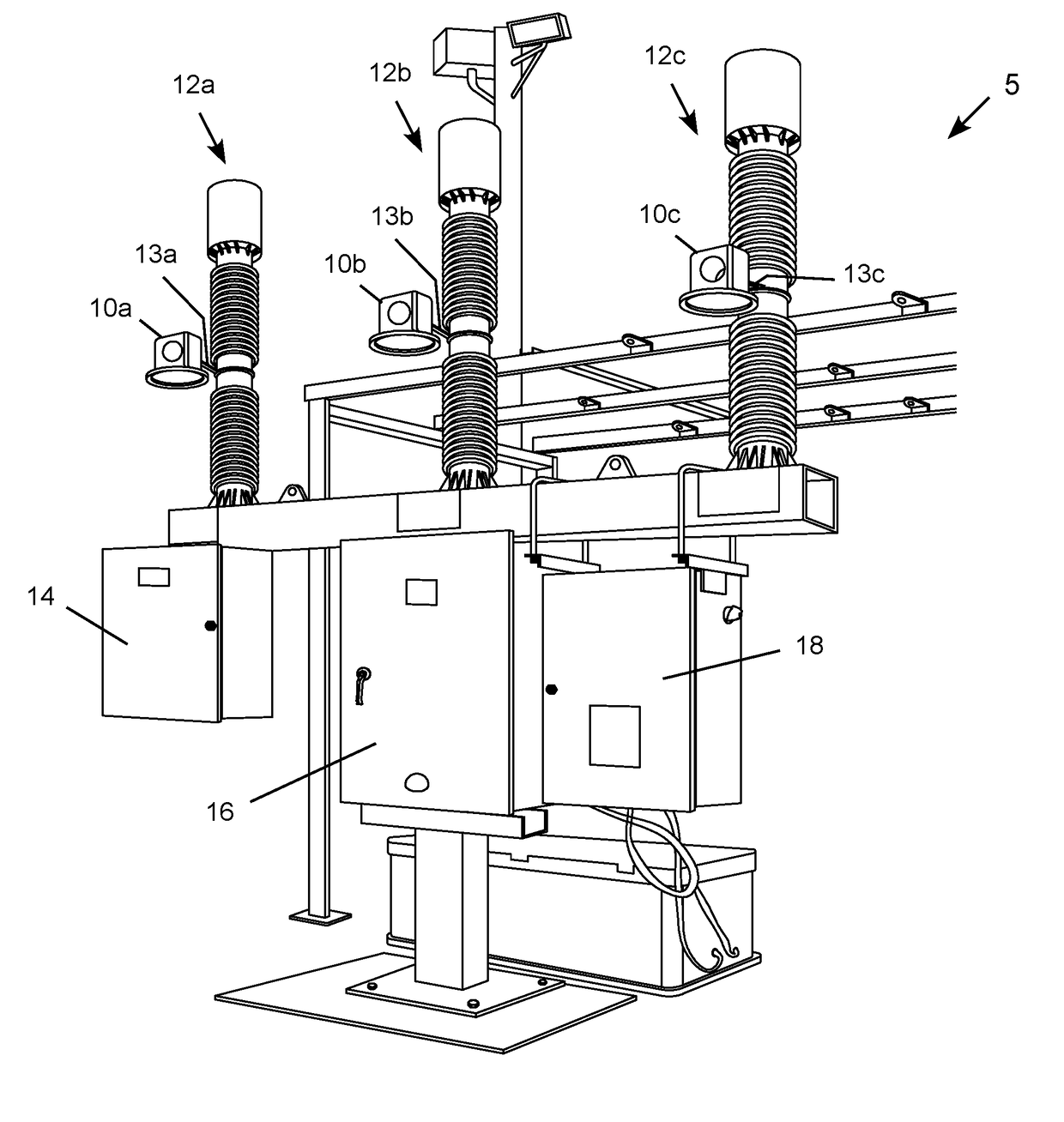
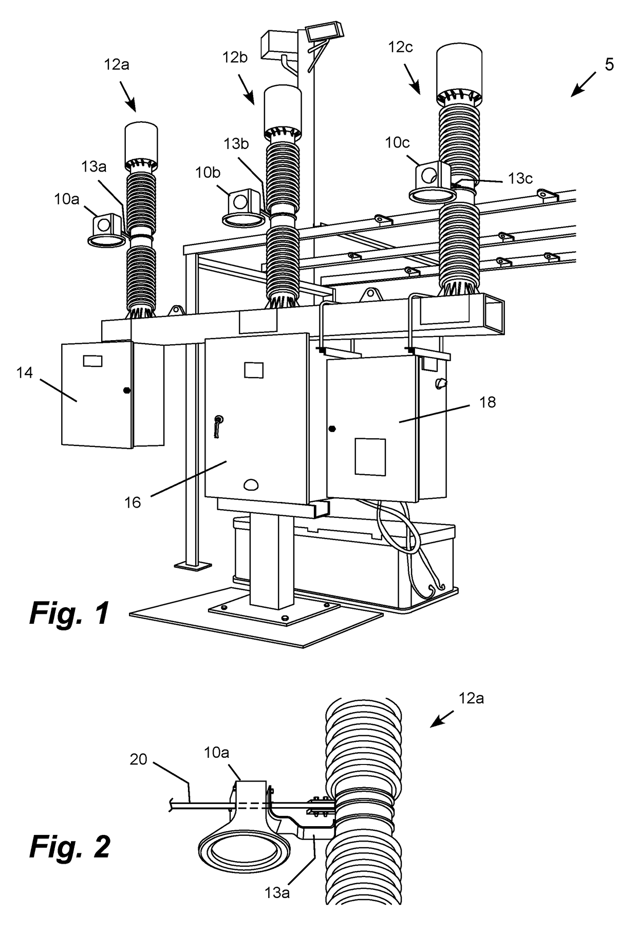
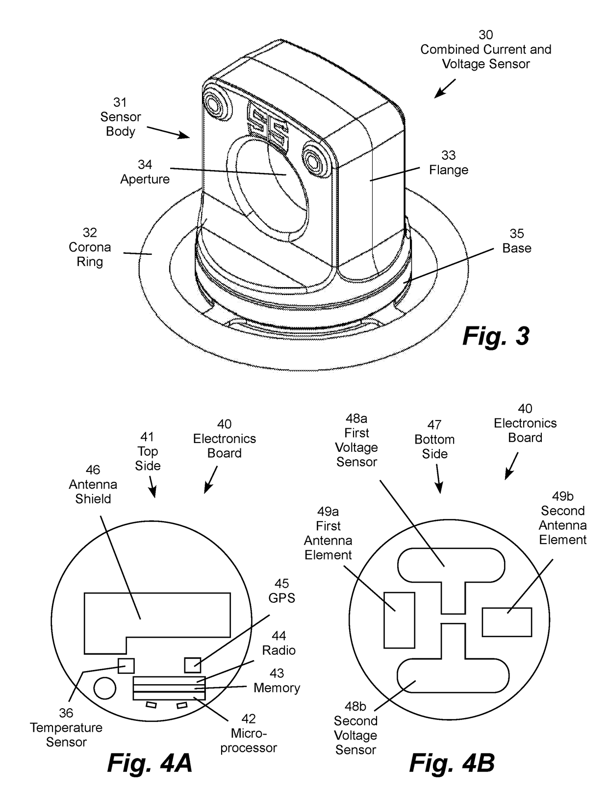
[0022]The present invention may be embodied in a high voltage electric power line monitor including a current sensor, a voltage sensor, an energy harvesting power supply, and a communication device. The combined electric current and voltage monitor is configured to be supported by a structure, such a sectionalizing switch disposed within an insulator cylinder. The switch also supports the power line monitored by the current and voltage sensors. The current sensor coil and an energy harvesting device (e.g., inductive coil) are configured to surround and be positioned transverse to the monitored power line with the power line extending through an aperture formed by the current sensor. The voltage sensor is carried on an electronics board configured to be positioned parallel to the monitored power line, typically below the current sensor. Both the current sensor and the voltage sensor are configured to positioned adjacent to, but spaced apart from, the monitored power line. The current...


PUM


Abstract

A high voltage electric power line monitor includes a current sensor, and voltage sensor, an energy harvesting power supply, and communication device. The monitor is configured to be supported by a structure, such a sectionalizing switch disposed within an insulator cylinder. The current sensor coil and an energy harvesting coils are configured to surround and be positioned transverse to the monitored power line with the power line extending through an aperture formed by the current sensor. A foil patch voltage sensor is carried on an electronics board configured to be positioned parallel to the monitored power line, typically below the current sensor. Both the current sensor and the voltage sensor are configured to positioned adjacent to, but spaced apart from, the monitored power line. The sensors are housed within a Faraday cage to shield the current sensor from electromagnetic contamination.

Description

REFERENCE TO RELATED APPLICATION[0001]This application claims filing priority to U.S. Provisional Patent Application Ser. No. 62 / 501,798 filed May 5, 2017, which is incorporated by reference.TECHNICAL FIELD[0002]The present invention relates to the field of high voltage electric power transmission and distribution systems and, more particularly, to a combined current and voltage electric power sensor with an onboard energy harvesting power supply and wireless communication device.BACKGROUND OF THE INVENTION[0003]At present, ring-type current transformers (“CTs”) are the most prevalent technology for measuring phase currents in three-phase electric power transmission and distribution lines. Conventional CTs are often placed in physical contact with the monitored power line conductor, which results in excessive heating of the CT and the power line. Excessive heating can adversely impact electronics in the CT and limit the current carrying capacity of the power line. Conventional CTs a...

Claims


Application Information

Patent Timeline
IPC IPC(8): G01R19/25G01R21/06G01R15/14G01R15/18H05K9/00G06F1/26G01R21/133
CPCG01R19/2513G01R21/06G01R15/142G01R15/181H05K9/0081G06F1/26G01R21/133G01R15/16G01R15/183G01R15/18
Inventor KEISTER, JOSHROSTRON, JOSEPH RFAN, JIYUANTRAN, TAN
Owner SOUTHERN STATES
Features
  • Generate Ideas
  • Intellectual Property
  • Life Sciences
  • Materials
  • Tech Scout
  • Unparalleled Data Quality
  • Higher Quality Content
  • 60% Fewer Hallucinations
Learn More