Multi-camera vision system and method of monitoring

a multi-camera and vision system technology, applied in the field of multi-camera vision system and monitoring method, can solve the problems of increasing the cost and complexity of both data acquisition and processing, reducing the effectiveness of monitoring and intervention, and reducing so as to reduce the number of scan window sizes. , the effect of increasing the size of images

Active Publication Date: 2018-11-15
FOTONATION LTD
View PDF8 Cites 21 Cited by
  • Summary
  • Abstract
  • Description
  • Claims
  • Application Information

AI Technical Summary

Benefits of technology

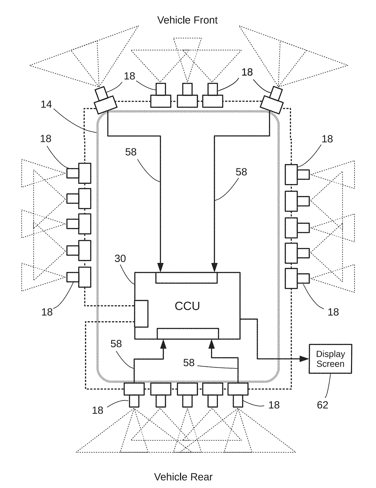
[0020]Compared to the field of view angle of the first scene image acquired from the first of the zones relatively close to the structure, field of view angles for multiple image scenes acquired from the second of the zones w

Problems solved by technology

These responses are often based on limited data sent from a single source, but for complex situations a range of more intensive data acquisition efforts are needed to monitor conditions and generate warnings of potential safety or security concerns.
Providing more comprehensive performance in these systems can increase cost as well as complexity of both data acquisition and processing.
Presently, assimilating and processing such high speed data rates for responses remains a costly challe

Method used


Image

  • Multi-camera vision system and method of monitoring
  • Multi-camera vision system and method of monitoring
  • Multi-camera vision system and method of monitoring

Examples


Embodiment Construction

[0035]Systems and methods for detecting objects, (e.g., pedestrians), as well as applications for such systems and methods are now described. Although specific details are set forth, embodiments of the invention may be practiced without these specific details. In other instances, well known structures and techniques have not been shown in detail in order not to obscure understanding of inventive features. Reference throughout the specification to “one embodiment” or “an embodiment” means that a particular feature, structure, or characteristic described in connection with the embodiment is included in at least one embodiment of the present invention. Thus, the appearance of the phrases “in one embodiment” or “in an embodiment” in various places throughout the specification are not necessarily referring to the same embodiment. The particular features, structures, or characteristics may be combined in any suitable manner in one or more embodiments. Embodiments of the invention are faci...


PUM


Abstract

A multi-camera vision system and method of monitoring. In one embodiment imaging systems provide object classifications with cameras positioned to receive image data from a field of view to classify an object among multiple classifications. A control unit receives classification or position information of objects and (ii) displays an image corresponding to a classified object relative to the position of the structure. An embodiment of a related method monitors positions of an imaged object about a boundary by continually capturing at least first and second series of image frames, each series comprising different fields of view of a scene about the boundary, with some of the image frames in the first series covering a wide angle field of view and some of the image frames in the second series covering no more than a narrow angle field of view.

Description

RELATED APPLICATIONS[0001]This application is related to U.S. Pat. No. 7,916,897, U.S. Pat. No. 8,170,294, U.S. Pat. No. 8,934,680; U.S. Pat. No. 8,872,887, U.S. Pat. No. 8,995,715, U.S. Pat. No. 8,385,610, U.S. Pat. No. 9,224,034, U.S. Pat. No. 9,242,602, U.S. Pat. No. 9,262,807, U.S. Pat. No. 9,280,810, U.S. Pat. No. 9,398,209 and U.S. patent application Ser. No. 13 / 862,372, filed Apr. 12, 2013, and U.S. patent application Ser. No. 14 / 971,725, filed Dec. 16, 2015, all assigned to the assignee of the present application and all of which are hereby incorporated by reference.FIELD OF THE INVENTION[0002]This invention relates to systems and methods for monitoring activity in a region surrounding a boundary or border. Embodiments of the invention provide real-time awareness of presence about a structure. In one example, a vision system monitors and displays roadway traffic activities about a moving vehicle.BACKGROUND OF THE INVENTION[0003]The demands for real-time situational awareness...

Claims


Application Information

Patent Timeline
IPC IPC(8): G06K9/00H04N7/18G06K9/20H04N5/232G06T11/60G06T7/70G06K9/62G06V10/147
CPCG06K9/00805H04N7/181G06K9/209H04N5/23293G06T2207/10004G06T11/60G06T7/70G06K9/6257G06T2207/30261H04N5/23238G06T2200/24G06V20/58G06V10/147H04N23/698H04N23/63H04N23/90
Inventor CORCORAN, PETER
Owner FOTONATION LTD
Why Eureka
Try Eureka