Capacitor-type power supply unit

a power supply unit and capacitor-type technology, applied in the field can solve the problems of shortened service life of capacitor-type power supply units, inability to achieve equal dividing of electric current flowing to electrical storage devices,

Active Publication Date: 2018-11-15
HONDA MOTOR CO LTD
View PDF0 Cites 17 Cited by
  • Summary
  • Abstract
  • Description
  • Claims
  • Application Information

AI Technical Summary

Benefits of technology

[0022]According to the present invention, it is possible to realize a capacitor-type power supply unit for which equal dividing of electric current flowing to electrical s

Problems solved by technology

In other words, since a difference arises in the voltages between the ends of the electrical storage device caused by the distance from the external connection part of each electrical storage device connected in parallel differing, equal dividing of the electric current

Method used


Image

  • Capacitor-type power supply unit
  • Capacitor-type power supply unit
  • Capacitor-type power supply unit

Examples


Embodiment Construction

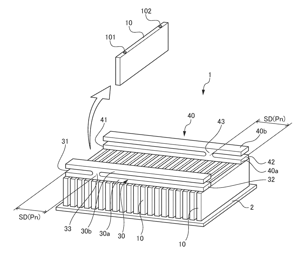
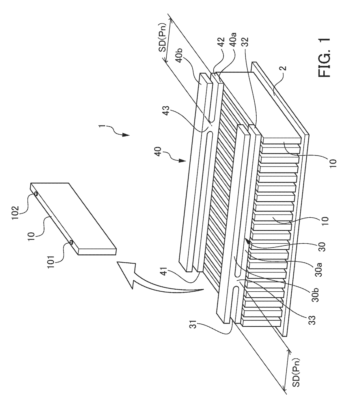
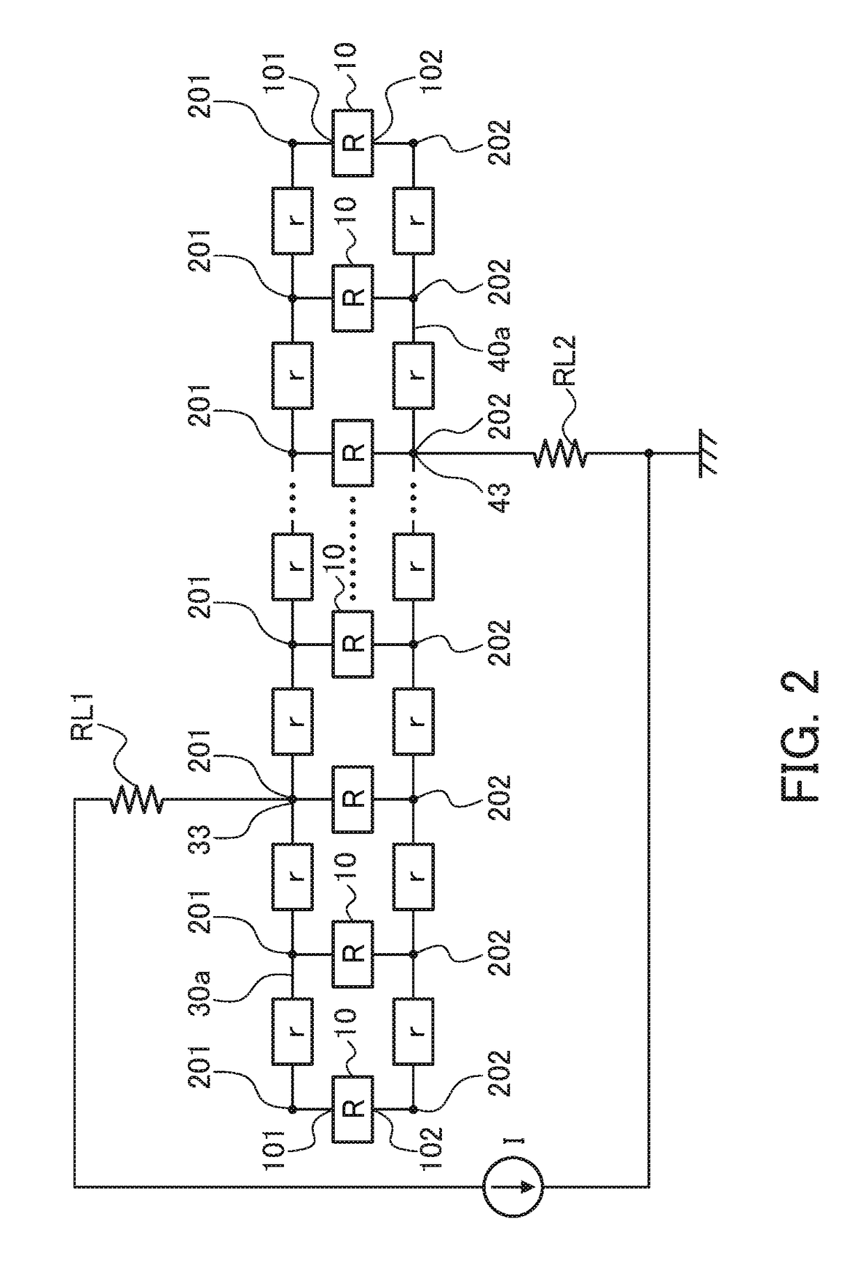
[0041]Hereinafter, a capacitor-type power supply unit of the present invention will be explained in detail by referencing the drawings. FIG. 1 is an external appearance perspective view showing an embodiment of the capacitor-type power supply unit of the present invention. FIG. 2 is a circuit diagram showing a general configuration of the capacitor-type power supply unit of the present invention. The electrical connection relationships of each part of the capacitor-type power supply unit in FIG. 1 are understood by referencing FIG. 2 where appropriate. In FIG. 1, a plurality of lithium ion capacitors 10, which are the respective electrical storage devices, are arranged in a row on a base 2, and the plurality of these lithium ion capacitors 10 are connected in series, whereby the capacitor-type power supply unit 1 is configured. The internal resistance of each of the lithium ion capacitors 10 is expressed as “R” in FIG. 2.

[0042]Each of the lithium ion capacitors 10 in the present exa...


PUM


Abstract

A capacitor-type power supply unit including:
    • a positive bus to which a plurality of capacitor is connected in parallel at each positive-electrode terminal thereof with maintaining equal intervals therebetween, and extends in a parallel direction; and an negative bus to which the plurality of capacitor is connected in parallel, at each negative-electrode terminal thereof with maintaining equal intervals therebetween, and extends in the parallel direction, in which the positive bus has a positive-electrode-side external connection part that is set at a position (SD) separated from the positive-electrode first end by a range of 20% to 30% of the total length in the longitudinal direction thereof, and the negative bus has an negative-electrode-side external connection part that is set at a position (SD) separated from the negative-electrode second end by a range of 20% to 30% of the total length in the longitudinal direction thereof.

Description

[0001]This application is based on and claims the benefit of priority from Japanese Patent Application Nos. 2017-096613 and 2018-090813, respectively filed on 15 May 2017 and 9 May 2018, the contents of which are incorporated herein by reference.BACKGROUND OF THE INVENTIONField of the Invention[0002]The present invention relates to a capacitor-type power supply unit capable of supplying accumulated electrical energy to outside.Related Art[0003]Conventionally, various types of capacitor-type power supply units have been proposed that supply to outside electrical energy that was stored in electrical storage devices which are connected in parallel. With such capacitor-type power supply units, it may be devised such that the electric current which has been equally divided as best possible is flowed to several electrical storage devices connected in parallel. This is in order to avoid the charge and discharge electric current from concentrating on a specific electrical storage device, an...

Claims


Application Information

Patent Timeline
IPC IPC(8): H01G11/50H01G9/042H01G11/06H01G4/228H01G4/38H01G11/12H01G11/72
CPCH01G4/38H01G11/12H01G11/72H01G11/86H01G11/50H01G9/042H01G11/06H01G4/228H01M50/502H01G11/10H01G11/76H01G11/82Y02E60/10
Inventor NAGAYOSHI, SHOGOWATANABE, SHINYASAITO, YASUHISASAITO, HITOSHIHIRAYAMA, SHINYUSAWAMURA, HIRONORI
Owner HONDA MOTOR CO LTD
Why Eureka
Try Eureka