
High efficiency electromagnetic vibration energy harvester

a high-efficiency, electromagnetic technology, applied in the direction of dynamo-electric machines, piezoelectric/electrostriction/magnetostriction machines, magnetic circuit shapes/forms/construction, etc., can solve the problem that energy conversion technology based on electromagnetic methods cannot be used universally in daily life, and achieve high energy conversion characteristics

Inactive Publication Date: 2018-11-15
ELECTRONICS & TELECOMM RES INST
View PDF5 Cites 0 Cited by
  • Summary
  • Abstract
  • Description
  • Claims
  • Application Information

AI Technical Summary

Benefits of technology

The patent text describes a technology for generating electric energy using permanent magnets and coils. However, this technology has low efficiency when the vibration frequency is low. The invention aims to provide a vibration / electric energy harvester that can achieve high energy conversion using a physical vibration source with small momentum. The invention offers a solution for generating electric energy in various environments. The technical effect is a high efficiency vibration / electric energy harvester that can be used for general purposes.

Problems solved by technology

Due to such a characteristic, the energy conversion technology based on the electromagnetic method cannot be used universally in daily life, and it can be used only in a limited field.

Method used


Image

  • High efficiency electromagnetic vibration energy harvester
  • High efficiency electromagnetic vibration energy harvester
  • High efficiency electromagnetic vibration energy harvester

Examples


Embodiment Construction

[0025]Hereinbelow, embodiments of the present invention will be described in detail so that those skilled in the art can easily carry out the present invention referring to the accompanying drawings. However, the present disclosure may be embodied in many different forms and is not limited to the embodiments described herein.

[0026]In the following description of the embodiments of the present invention, a detailed description of known functions and configurations incorporated herein will be omitted when it may make the subject matter of the present disclosure unclear. Parts not related to the description of the present disclosure in the drawings are omitted, and similar parts are denoted by similar reference numerals.

[0027]In the present disclosure, when an element is referred to as being “connected”, “coupled”, or “connected” to another element, it is understood to include not only a direct connection relationship but also an indirect connection relationship. Also, when an element ...


PUM


Abstract

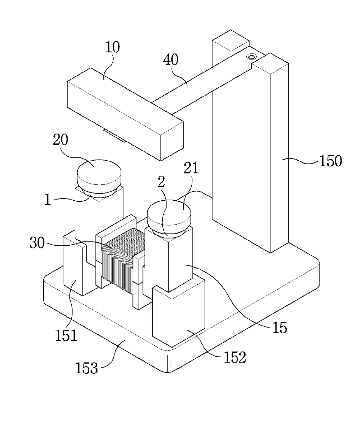
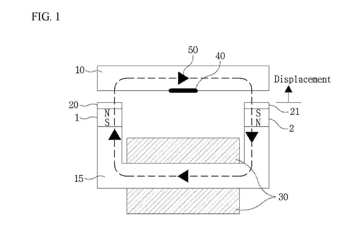
An energy harvester includes a first core vibrating in a predetermined direction; a second core being U-shaped and having opposite ends facing at least a part of the first core; a pair of magnetic bodies forming a magnetic flux connected between the first core and the second core; and a coil member wound on the second core to generate an induced current due to a magnetic flux change in the second core.

Description

CROSS-REFERENCE TO RELATED APPLICATION[0001]The present application claims priority to Korean Patent Application No. 10-2017-0059299, filed May 12, 2017, the entire content of which is incorporated herein for all purposes by this reference.BACKGROUND OF THE INVENTION1. Field of the Invention[0002]The present invention relates generally to an energy harvester and, more particularly, to an energy harvester for converting vibration energy into electric energy.2. Description of Related Art[0003]Energy harvesting technology is a technology that can convert kinetic energy or heat / light energy that may be inadvertently wasted in daily life into effective electric energy. The energy harvesting technology has recently been attracting interest as mobile communication terminal technology, wireless sensor network technology, and Internet of Thing (IoT) technology are actively being developed. In addition, since no environmental pollutants are generated during the energy conversion process, much...

Claims


Application Information

Patent Timeline
Patent Type & Authority Applications(United States)
IPC IPC(8): H02K35/02H02K1/06H02J5/00H10N30/20
CPCH02K35/02H02K1/06H02J5/00H02K35/06H02N2/18H10N30/20
Inventor CHOI, WON KYUKIM, HYUN SEOKMO, SANG HYUNPARK, CHAN WONHAN, KYU WON
Owner ELECTRONICS & TELECOMM RES INST
Learn More