Electrical power generation and distribution

Active Publication Date: 2018-11-15
ENERGY PRODUCING SYST OF AMERICA LLC
View PDF0 Cites 7 Cited by
  • Summary
  • Abstract
  • Description
  • Claims
  • Application Information

AI Technical Summary

Benefits of technology

[0007]Responsive to the foregoing challenges, Applicant has developed an innovative electric power system comprising: an electric battery subsystem; a switching subsystem coupled to the electric battery subsystem; an electrically powered function control subsystem coupled to the switching subsystem and the electric battery subsystem, said electrically powered function control subsystem including a processor and memory; a capacitor subsystem coupled to the electrically powered function control subsystem; an electric motor coupled to the electr

Problems solved by technology

The consumption of electrical power worldwide is vast and will likely continue to grow as traditionally non-electrical powered machines are replaced with electrically powered counterparts.
Developed countries all have sophisticated electrical power generation and distribution systems deployed nationwide sometimes referred to as the “power grid.” While the grid is widely used and ubiquitous, it is not always available, and may not provide the lowest cost of power

Method used


Image

  • Electrical power generation and distribution
  • Electrical power generation and distribution
  • Electrical power generation and distribution

Examples


Embodiment Construction

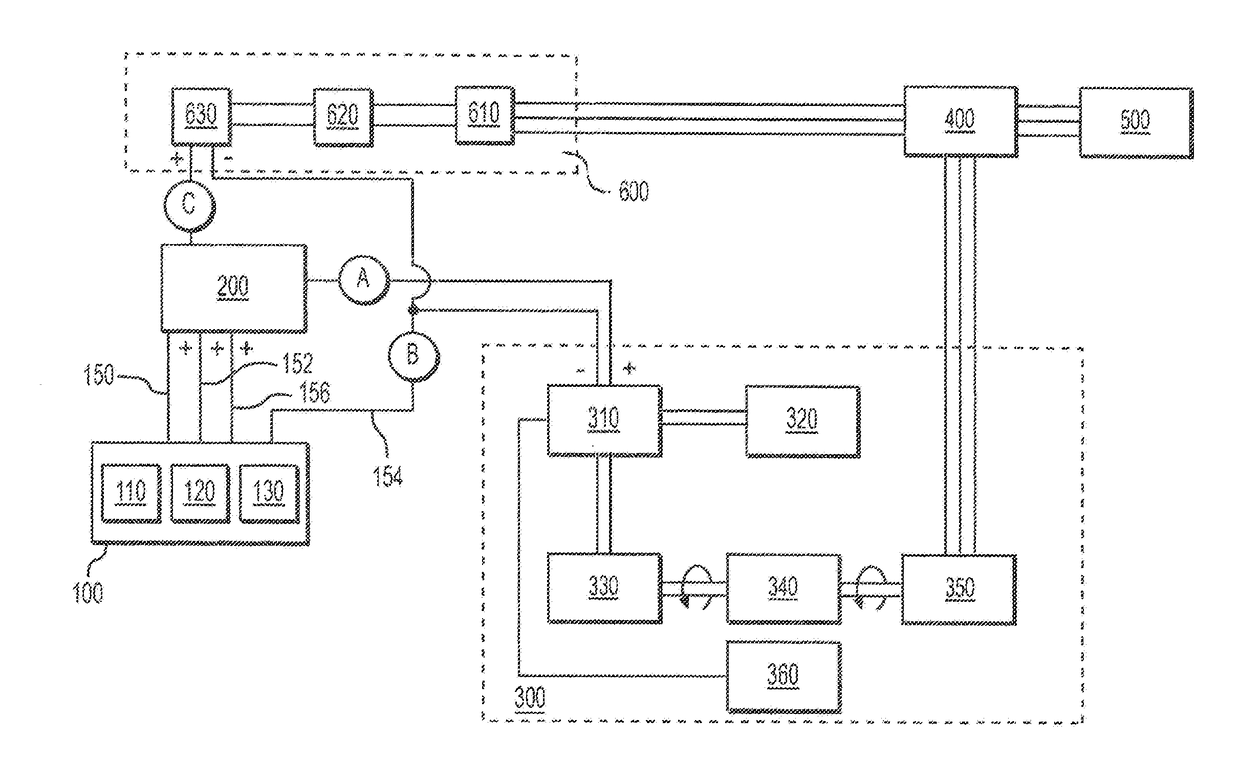
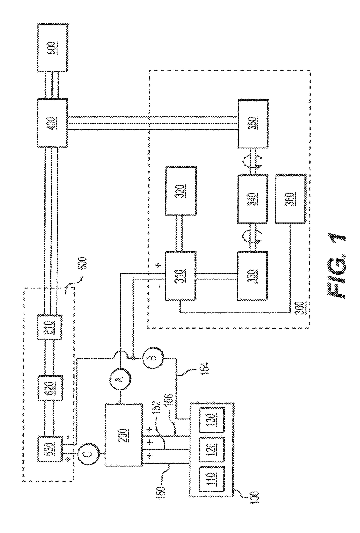
[0019]Reference will now be made in detail to embodiments of the present invention, examples of which are illustrated in the accompanying drawings. With reference to FIG. 1, in a first embodiment of the invention, a direct current (DC) battery system 100 may be electrically connected by a switching subsystem 200 to an alternating current (AC) electric power generation system 300. The power generation system 300 may be electrically connected to an AC power distribution subsystem 400, which in turn may be connected to a load source 500 and a battery charging system 600. The battery charging system 600 may be connected to the battery system 100 through the switching subsystem 200.

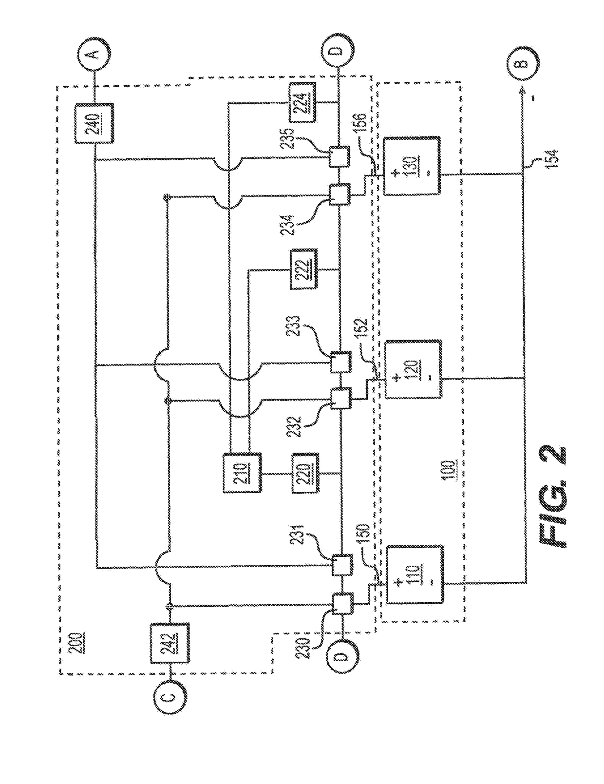
[0020]The DC battery system 100 may include first, second and third battery subsystems or banks 110, 120 and 130 that may each be comprised of a plurality of individual batteries and battery cells. The individual batteries and battery cells comprising each of the battery subsystems may be connected in series. ...


PUM


Abstract

Systems and methods of generating, storing and/or distributing electric power are disclosed. The system may include two or more direct current battery subsystems, a direct current motor/alternating current generator combination, an electric power distribution network, and battery recharging elements. One battery subsystem may power an alternating current generator while the other battery subsystem charges using a portion of the generated power. Excess power may service other electric loads. The roles of the battery subsystems may be switched periodically between charging and powering, repeatedly. A gear box may connect the electric motor and generator to adjust the relative rotational speeds of each for optimal performance of the system.

Description

CROSS REFERENCE TO RELATED APPLICATIONS[0001]This application relates to and claims the priority of U.S. patent application Ser. No. 15 / 400,662 which was filed Jan. 6, 2017.FIELD OF THE INVENTION[0002]The present invention relates generally to systems and methods of generating, storing and / or providing electrical energy.BACKGROUND OF THE INVENTION[0003]The consumption of electrical power worldwide is vast and will likely continue to grow as traditionally non-electrical powered machines are replaced with electrically powered counterparts. For example, electrically powered vehicles, and in particular passenger automobiles, are becoming more and more prevalent on nations' road systems. One popular electric automobile manufacturer in the United States with annual sales of roughly fifty thousand units in 2015-16 has announced its intention to grow the number of sales to five hundred thousand units within just a few years.[0004]The impetus for switching to electrical power is multifaceted...

Claims


Application Information

Patent Timeline
IPC IPC(8): H02K47/04B60L11/12H02J7/00B60L50/15
CPCH02K47/04B60L11/12H02J7/0068H02J3/28H02J3/32B60L55/00B60L53/63B60L58/18Y02T10/70Y02T10/7072Y02T90/12Y04S10/126Y02E60/00B60L50/15
Inventor FEATHERLY, ROBERT J.T ONCHICH, RUDOLPH M.
Owner ENERGY PRODUCING SYST OF AMERICA LLC
Why Eureka
Try Eureka