Method for manufacturing shunt resistor

Active Publication Date: 2018-11-22
SANCALL
View PDF13 Cites 2 Cited by
  • Summary
  • Abstract
  • Description
  • Claims
  • Application Information

AI Technical Summary

Benefits of technology

[0029]The manufacturing method of shunt resistor according to the sixth aspect of the present invention makes it possible to efficiently manufacture a shunt resistor that can improve

Problems solved by technology

More specifically, when the temperature of the shunt resistor excessively increases, there is a possibility that the actual value of resistance of the shunt resistor fluctuates from the predetermined value of resistance set beforehand and/or other members located near the resistance alloy plate member are adversely affected.
In particular, when the shunt resistor is utilized in electric devices in which a large current flows, s

Method used


Image

  • Method for manufacturing shunt resistor
  • Method for manufacturing shunt resistor
  • Method for manufacturing shunt resistor

Examples


embodiment 1

[0041]Hereinafter, one embodiment of a method for manufacturing a shunt resistor according to the present invention is described with reference to the accompanying drawings.

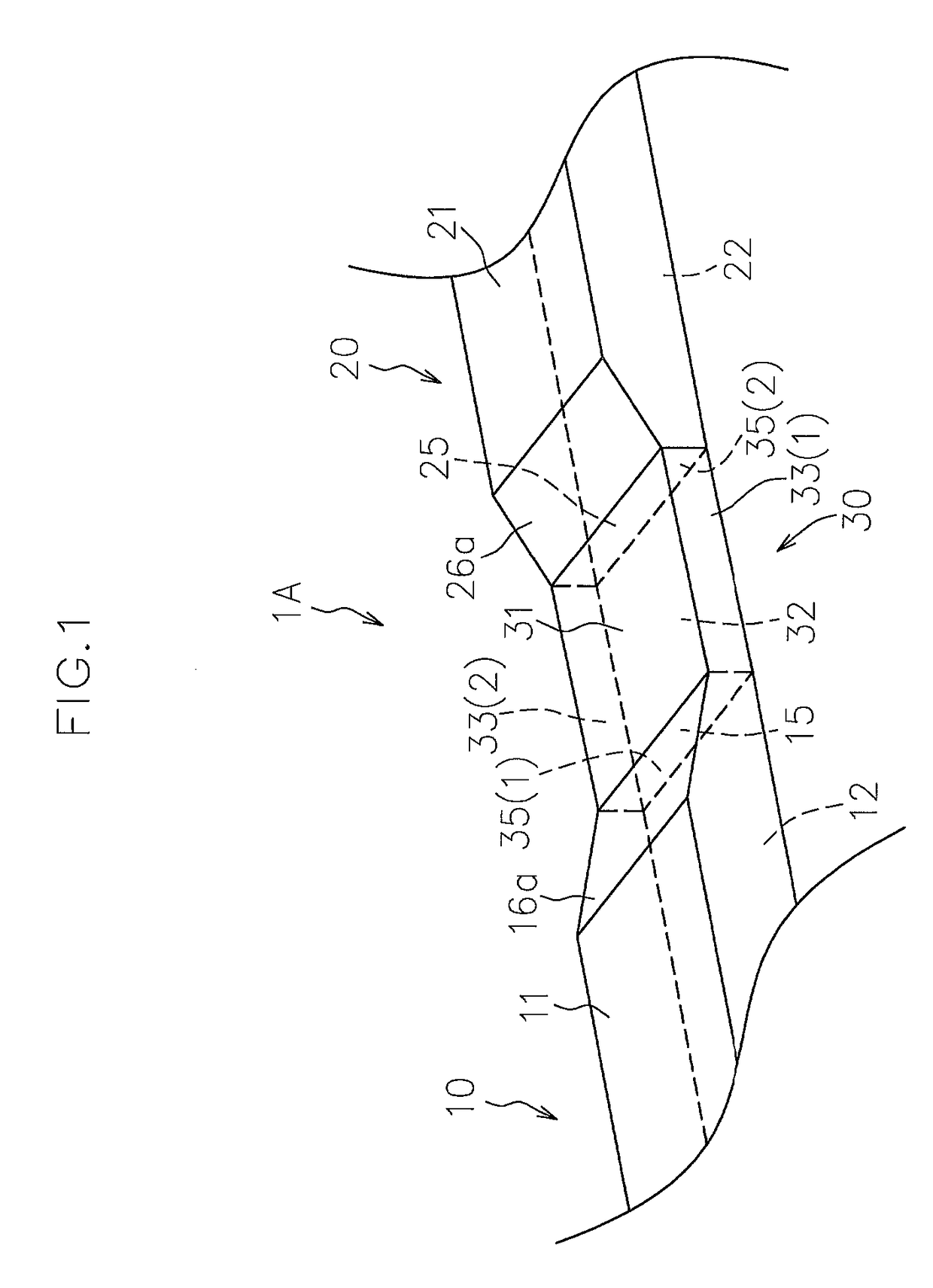
[0042]FIG. 1 illustrates a perspective view of a shunt resistor 1A manufactured by the manufacturing method according to this embodiment.

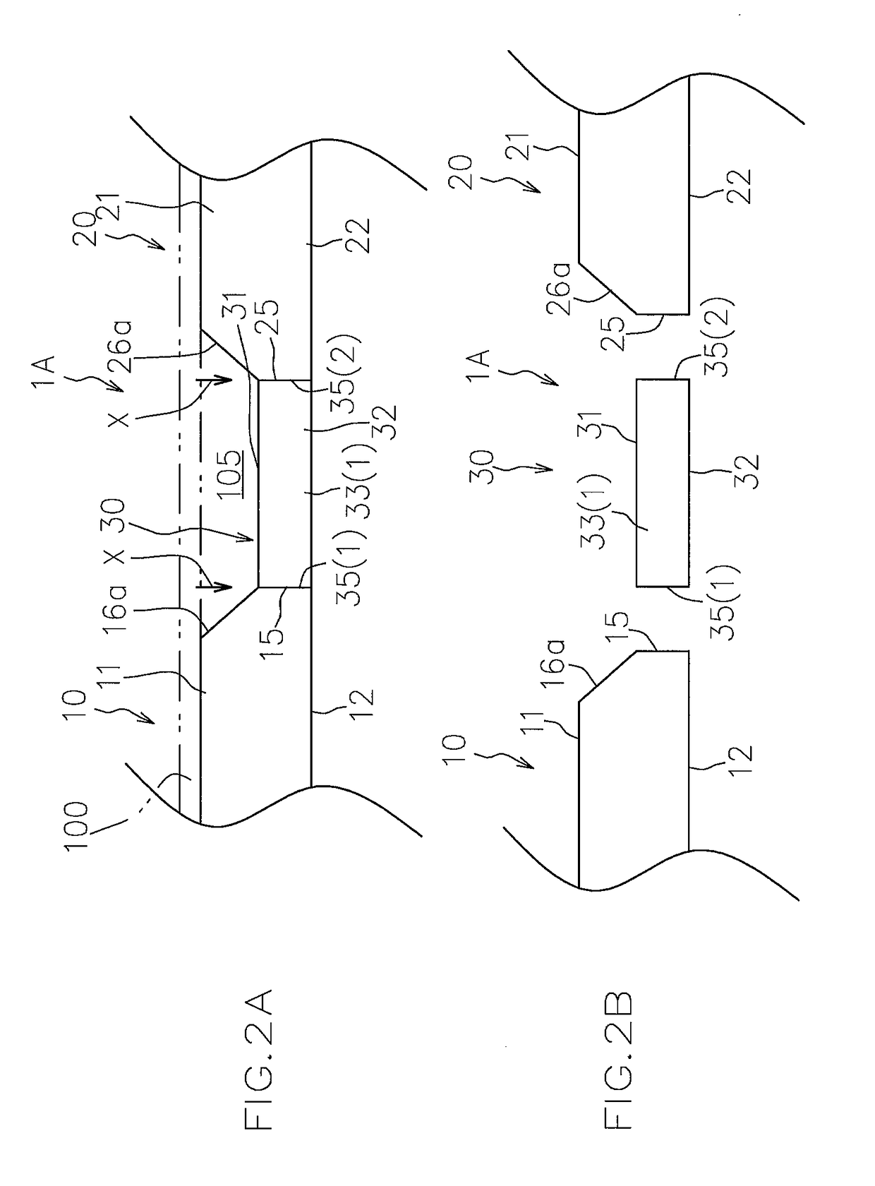
[0043]FIGS. 2A and 2B illustrate a side view and an exploded side view, respectively, of the shunt resistor 1A.

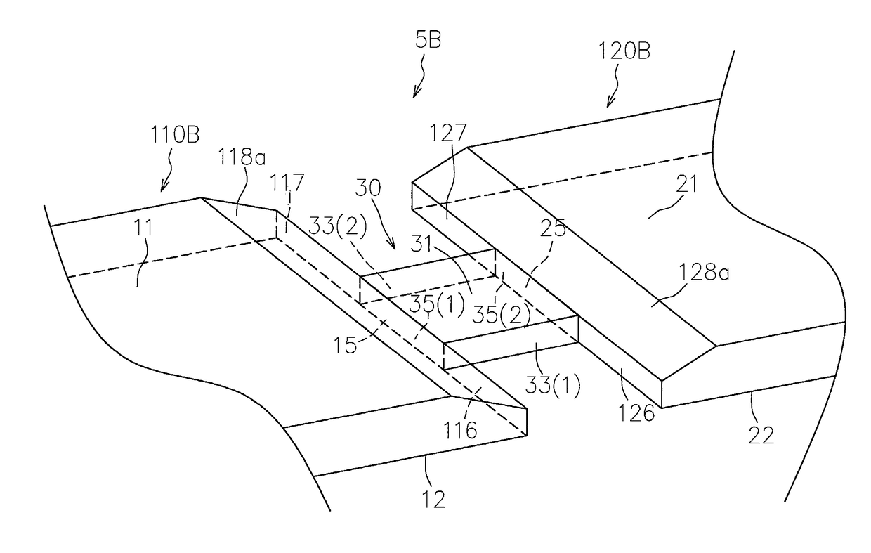
[0044]As illustrated in FIG. 1, FIG. 2A, and FIG. 2B, the shunt resistor 1A has a resistance alloy plate member 30 and first and second conductors 10, 20 which are respectively joined to one side and the other side in the current flow direction of the resistance alloy plate member 30.

[0045]The first and second conductors 10, 20 are formed of a conductive member and, for example, a Cu metal plate member is preferably used.

[0046]The first and second conductors 10, 20 are provided with a pair of detection terminals (not illustrated) that are located near the resistance all...

embodiment 2

[0080]Hereinafter, another embodiment of the method for manufacturing a shunt resistor according to the present invention is described with reference to the accompanying drawings.

[0081]FIGS. 4A and 4B illustrate a side view and an exploded side view, respectively, of a shunt resistor 2A manufactured by the manufacturing method according to this embodiment.

[0082]In the figures, the same members as those in Embodiment 1 are designated by the same reference numerals and a description thereof is omitted as appropriate.

[0083]The shunt resistor 2A of this embodiment has first and second conductors 50, 60 in place of the first and second conductors 10, 20 as compared with the shunt resistor 1A of Embodiment 1.

[0084]The plate thickness of at least either one of the first and second conductors 50, 60 is set larger than the plate thickness of the resistance alloy plate member 30 as with Embodiment 1.

[0085]In the embodiment illustrated in the figures, the plate thickness of both the first and ...

embodiment 3

[0094]Hereinafter, still another embodiment of the method for manufacturing a shunt resistor according to the present invention is described with reference to the accompanying drawings.

[0095]FIGS. 6A and 6B illustrate a side view and an exploded side view, respectively, of a shunt resistor 3A manufactured by the manufacturing method according to this embodiment.

[0096]In the figures, the same members as those in Embodiments 1 and 2 are designated by the same reference numerals and a description thereof is omitted as appropriate.

[0097]The shunt resistor 3A has a resistance alloy plate member 90 and first and second conductors 70, 80 which are respectively joined to one side and the other side in the current flow direction of the resistance alloy plate member 90.

[0098]The plate thickness of at least either one of the first and second conductors 70, 80 is set larger than the plate thickness of the resistance alloy plate member 90 as with Embodiments 1 and 2.

[0099]In the embodiment illus...


PUM

PropertyMeasurementUnit
Thicknessaaaaaaaaaa
Electrical resistanceaaaaaaaaaa

Abstract

In manufacturing method of shunt resistor according to the present invention, at least one of first and second conductors that is thicker than a resistance alloy plate member includes a joining surface abutted to the resistance alloy plate member with their edges on one side in a plate-thickness direction being aligned with each other, a first inclined surface that is gradually located on one side in the plate-thickness direction from the joining surface toward the side opposite to the resistance alloy plate member in the plate-surface direction, and a first plate surface extending to the side opposite to the resistance alloy plate member in the plate-surface direction from the first inclined surface. Electron beams or laser is emitted to the joining surfaces of the conductor having the larger thickness and the resistance alloy plate member from one side in the plate-thickness direction to weld the joining surfaces.

Description

FIELD OF THE INVENTION[0001]The present invention relates to a method for manufacturing a shunt resistor.BACKGROUND ART[0002]The shunt resistor is a component having a resistance alloy plate member and first and second conductors which are individually joined to both sides of the resistance alloy plate member, in which the value of resistance between the first and second conductors is set to a predetermined value beforehand.[0003]The shunt resistor is connected in series to an electric circuit which is a current value detection target in order to detect the current value of the circuit by measuring a voltage value between the first and second conductors in the shunt resistor.[0004]When the shunt resistor is used, it is preferable to suppress the temperature increase of the shunt resistor as much as possible.[0005]More specifically, when the temperature of the shunt resistor excessively increases, there is a possibility that the actual value of resistance of the shunt resistor fluctu...

Claims


Application Information

Patent Timeline
IPC IPC(8): B23K15/00B23K26/21G01R15/00H01C17/00
CPCB23K15/0046B23K26/21G01R15/00H01C17/00B23K15/006B23K26/242B23K26/26B23K33/004B23K2101/38G01R1/203H01C1/144H01C1/12H01C17/07H01C17/28H01C7/06B23K15/00H01C13/00
Inventor WAKABAYASHI, SHOJIROKOBAYAKAWA, HIROYA
Owner SANCALL
Why Eureka
Try Eureka